Honda CR-V: Driveline/Axle
Honda CR-V (2006–2011) Service Manual / Transaxle / Driveline/Axle
Special Tools
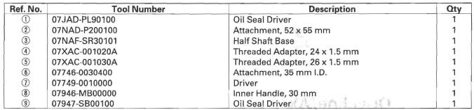
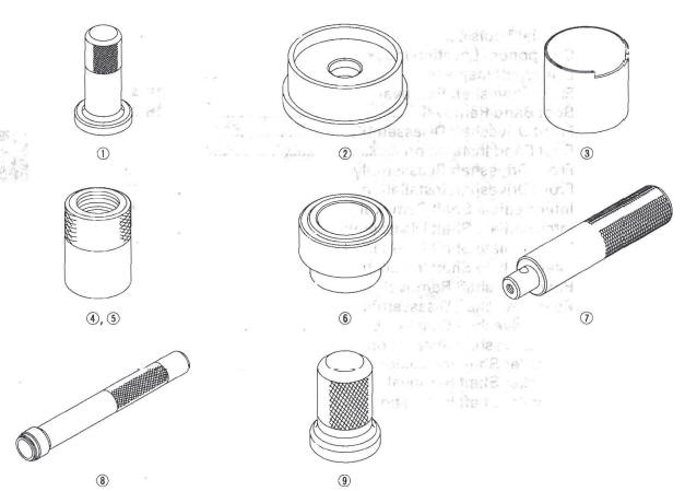
- Oil Seal Driver
- Attachment, 52 x 55 mm
- Half Shaft Base
- Threaded Adapter, 24 x 1.5 mm
- Threaded Adapter, 26 x 1.5 mm
- Attachment, 35 mm I.D.
- Driver
- Inner Handle, 30 mm
- Oil Seal Driver
Component Location Index
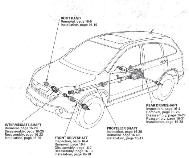
- BOOT BAND
- Removal
- Installation
- INTERMEDIATE SHAFT
- Removal
- Disassembly
- Reassembly
- Installation
- FRONT DRIVES HAFT
- Inspection
- Removal
- Disassembly
- Reassembly
- Installation
- PROPELLER SHAFT
- Inspection
- Removal
- Installation
- REAR DRIVESHAFT
- Inspection
- Removal
- Disassembly
- Reassembly
- Installation
- Driveshaft Inspection
- Front Driveshaft Disassembly
- Boot Band Installation
- Front Driveshaft Reassembly
- Front Driveshaft Installation
- Intermediate Shaft
- Rear Driveshaft
- Propeller Shaft
READ NEXT:
 Driveshaft Inspection
1. Check the inboard boot (A) and the outboard boot
(B) on the driveshaft (C) for cracks, damage, leaking
grease, and loose boot bands (D). If any damage is
found, replace the boot and boot bands.
2.
Front Driveshaft Disassembly
Special Tools Required
Threaded adapter, 26 x 1.5 mm 07XAC-001030A
Slide hammer, 5/8"-18 UNF, commercially available
Inboard Joint Side
1. Remove the set ring (A) from the inboard joint.
2. Remov
Boot Band Installation
Special Tools Required
Boot band tool, KD-3191 or equivalent, commercially
available
Boot band pliers, Kent-Moore J-35910 or equivalent,
commercially available
Double Loop Type
1. Fit the boot ends on
SEE MORE:
DTC 86: F-CAN Communication
1. Turn the ignition switch ON (II).
2. Clear the DTC with the HDS.
3. Turn the ignition switch OFF.
4. Start the engine.
5. Wait at least 5 seconds.
6. Check for DTCs with the HDS.
Is DTC 86 indicated?
YES-Go to step 7.
NO-Intermittent failure, the system is OK at this time. Check for a loos
Text Data Display Function
Each time you press the TITLE
button, the display mode shows you
in sequence, the folder name, the file
name, the artist name, the album
name, the song name, or name off
(which turns off the text display).
The display shows up to 16
characters of the selected data. If the
text data ha
© 2016-2026 Copyright www.hcrv.net
