Honda CR-V: Front Driveshaft Disassembly
Special Tools Required
- Threaded adapter, 26 x 1.5 mm 07XAC-001030A
- Slide hammer, 5/8"-18 UNF, commercially available
Inboard Joint Side
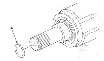
1. Remove the set ring (A) from the inboard joint.
2. Remove the boot bands. Be careful not to damage the boot.
3. Make marks (A) on each roller (B) and inboard joint (C) to identify the locations of rollers and grooves in the inboard joint. Then remove the inboard joint on the a shop towel (D). Be careful not to drop the rollers when separating them from the inboard joint.
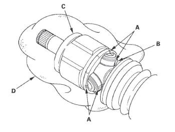
4. Make marks (A) on the rollers (B) and spider (C) to identify the locations of the rollers on the spider, then remove the rollers.
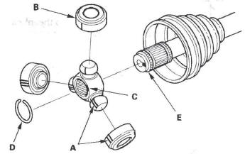
5. Remove the circlip (D).
6. Mark the spider and driveshaft (E) to identify the position of the spider on the shaft.
7. Remove the spider.
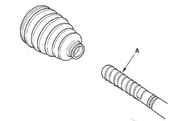
8. Wrap the splines on the drives haft with vinyl tape (A) to prevent damage to the boot.
9. Remove the inboard boot. Be careful not to damage the boot.
10. Remove the vinyl tape.
Outboard Joint Side
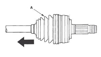
1. Remove the boot bands. Be careful not to damage the boot.
2. Slide the outboard boot (A) partially to the inboard joint side. Be careful not to damage the boot.
3. Wipe off the grease to expose the driveshaft and the outboard joint inner race.
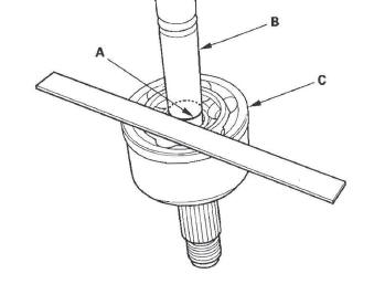
4. Make a mark (A) on the driveshaft (B) at the same level as the outboard joint rim (C).
5. Securely clamp the driveshaft in a bench vise with a shop towel.
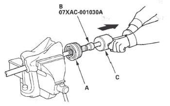
6. Remove the outboard joint (A) using the threaded adapter (B) and a commercially available 5/8" - 18 UNF slide hammer (C).
7. Remove the driveshaft from the bench vise.
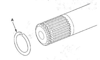
8. Remove the stop ring (A) from the drives haft.
9. Wrap the splines on the driveshaft with vinyl tape (A) to prevent damaging the boot.
10. Remove the outboard boot. Be careful not to damage the boot.
11. Remove the vinyl tape.
READ NEXT:
 Boot Band Installation
Special Tools Required
Boot band tool, KD-3191 or equivalent, commercially
available
Boot band pliers, Kent-Moore J-35910 or equivalent,
commercially available
Double Loop Type
1. Fit the boot ends on
Front Driveshaft Reassembly
Exploded View
NOTE: Refer to the Exploded View as needed during
this procedure.
Inboard Joint Side
1. Wrap the splines with vinyl tape (A) to prevent
damaging to the inboard boot.
2. Install the inb
Front Driveshaft Installation
1. Apply grease to the contact area (A) of the outboard
joint and front wheel bearing.
NOTE: Failure to apply grease may cause excessive
noise and vibration.
2. Install a new set ring (A) onto the s
SEE MORE:
Improving Fuel Economy
Vehicle Maintenance
A properly maintained vehicle
maximizes fuel economy. Poor
maintenance can significantly reduce
fuel economy. Always maintain your
vehicle according to the maintenance
messages displayed on the multiinformation display.
For example:
Use the recommended viscosity
mo
DLC Circuit Troubleshooting
NOTE: Make sure the HDS and the DLC cable of the
HDS is not defective.
1. Turn the ignition switch OFF.
2. Connect the HDS to the DLC.
NOTE: Make sure the HDS is properly connected to
the DLC.
3. Turn the ignition switch ON (II). and read the HDS.
Does the HDS identify the vehicle?
YES-Go to ste
