Honda CR-V: Front Driveshaft Installation
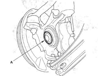
1. Apply grease to the contact area (A) of the outboard joint and front wheel bearing.
NOTE: Failure to apply grease may cause excessive noise and vibration.
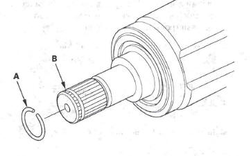
2. Install a new set ring (A) onto the set ring groove (B) of the driveshaft (left driveshaft).
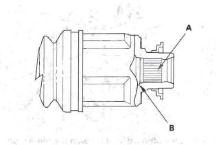
3. Apply 0.5-1.0 g (0.02-0.04 oz) of grease to the whole splined surface (A) of the right driveshaft.
After applying grease, remove the grease from the splined grooves at intervals of 2-3 splines and from the set ring groove (B) so that air can bleed from the intermediate shaft.
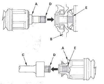
4. Clean the areas where the driveshaft contacts the differential thoroughly with solvent or brake cleaner, and dry with compressed air. Insert the inboard end (A) of the driveshaft into the differential (B) or intermediate shaft (C) until the set ring (D) locks in the groove (E).
5. Install the outboard joint (A) into the front hub (B).
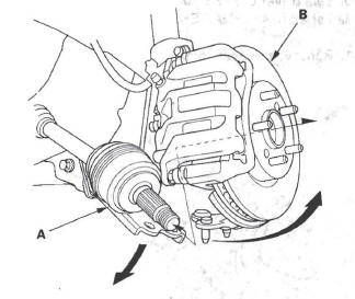
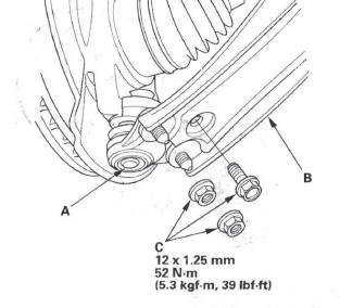
6. Install the knuckle (A) onto the lower arm (B).
Then tighten the nuts and bolt (C) to the torque specification.
7. Install a new spindle nut (A), then tighten the nut.
After tightening; use a drift to stake the spindle' nut shoulder (B) against the driveshaft.
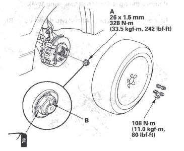
8. Clean the mating surfaces of the brake disc and the front wheel, then install the front wheel.
9. Turn the front wheel by hand, and make sure there is no interference between the driveshaft and surrounding parts.
10. Refill the transmission with the recommended automatic transmission fluid.
11. Check the front wheel alignment, and adjust it if necessary.
READ NEXT:
 Intermediate Shaft
Intermediate Shaft Removal
1. Drain the automatic transmission fluid. Reinstall the drain plug with a
new washer.
2. Remove the right driveshaft.
3. Remove the flange bolt (A) and two dowel bolts (
Rear Driveshaft
Rear Driveshaft Removal
1. Raise the vehicle on a lift, and remove the rear
wheels.
2. Lift up the locking tab (A) on the spindle nut (B),
then remove the nut.
3. Drain the differential fluid.
4. R
Propeller Shaft
Propeller Shaft Inspection
Universal Joint and Boots
1. Set the parking brake, then shift the transmission to
the N position.
2. Raise the vehicle on a lift.
3. Check the center support bearing (A)
SEE MORE:
Headlight Adjustment
CAUTION
Headlights become very hot during use; do not
touch them or any attaching hardware immediately
after they have been turned off.
Before adjusting the headlights:
Park the vehicle on a level surface.
Make sure the tire pressures are correct.
The driver or someone who weighs the same should
Protecting Children General Guidelines
Children depend on adults to protect
them. However, despite their best
intentions, many adults do not know
how to properly protect child passengers.
If you have children, or ever need to
drive with a child in your vehicle, be
sure to read this section. It begins
with important gener
