Honda CR-V: Rear Driveshaft
Rear Driveshaft Removal
1. Raise the vehicle on a lift, and remove the rear wheels.
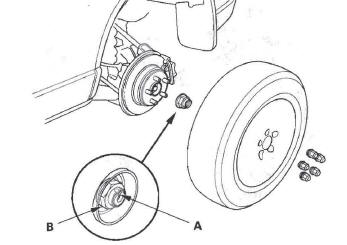
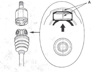
2. Lift up the locking tab (A) on the spindle nut (B), then remove the nut.
3. Drain the differential fluid.
4. Remove the rear driveshaft inboard joint from the rear differential assembly.
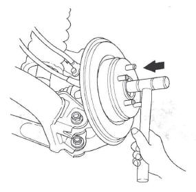
5. Disconnect the rear driveshaft outboard joint from the trailing arm and rear wheel hub using a plastic hammer or a puller if necessary.
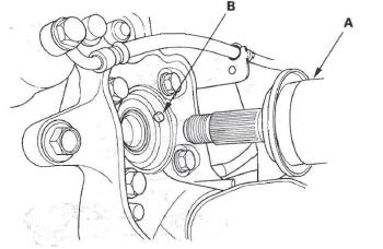
6. Remove the rear driveshaft (A).
NOTE
- Be careful not to damage the ABS wheel sensor (B).
- Pull on the outer joint. Do not pull on the driveshaft because the joint may come apart.
Rear Driveshaft Disassembly
Special Tools Required
- Threaded adapter, 24 x 1.5 mm 07XAC-001020A
- Slide hammer, 5/8"-18 UNF, commercially available
Inboard Joint Side (Japan-built Models)
NOTE:
- Due to the amount of work required to replace one damaged boot, it is best to replace both boots at the same time.
- These instructions are for the inboard joint. The same procedure applies to the outboard joint.
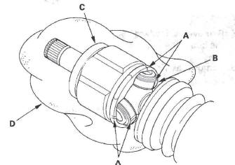
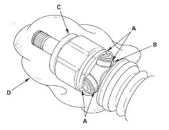
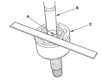
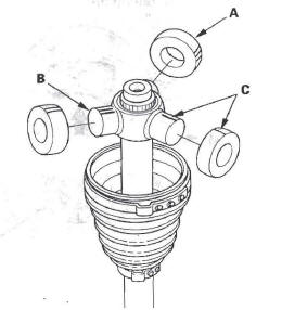
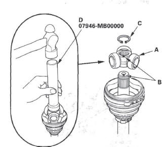
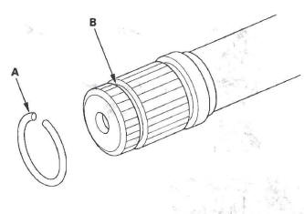
1. Remove the set ring (A) from the inboard joint.
2. Remove the boot bands. Be careful not to damage the boot.
3. Make a mark (A) on each roller (B) and inboard joint (C) to identify the locations of rollers and grooves in the inboard joint. Then remove the inboard joint on a shop towel (D). Be careful not to drop the rollers when separating them from the inboard joint.
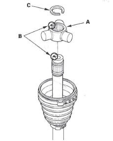
4. Make marks (A) on the rollers (B) and spider (C) to identify the locations of the rollers on the spider, then remove the rollers.
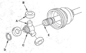
5. Remove the circlip (D).
6. Mark the spider (C) and driveshaft (E) to identify the position of the spider on the shaft.
7. Remove the spider (C).
8. Wrap the splines on the drives haft with vinyl tape (A) to prevent damaging to the boot.
9. Remove the inboard boot. Be careful not to damage the boot.
10. Remove the vinyl tape.
Inboard Joint Side (US-built Models)
1. Remove the set ring (A) from the inboard joint.
2. Remove the boot bands. Be careful not to damage the boot and dynamic damper.
3. Make a mark (A) on each roller (B) and inboard joint (C) to identify the locations of rollers and grooves in the inboard joint. Then remove the inboard joint on a shop towel (D). Be careful not to drop the rollers when separating them from the inboard joint.
4. Remove the circlip (A).
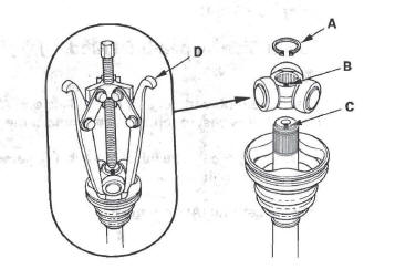
5. Make a mark on the spider (B) and drives haft (C) to identify the position of the spider on the shaft.
6. Remove the spider and rollers using a commercially available bearing remover (D).
7. Wrap the splines on the driveshaft with vinyl tape (A) to prevent damaging to the boot.
8. Remove the inboard boot. Be careful not to damage the boot.
9. Remove the vinyl tape.
Outboard Joint Side
1. Remove the boot bands. Be careful not to damage the boot.
2. Slide the outboard boot (A) partially to the inboard joint side. Be careful not to damage the boot.
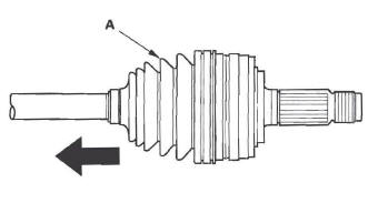
3. Wipe off the grease to expose the driveshaft and the outboard joint inner race.
4. Make a mark (A) on the driveshaft (B) at the same level as the outboard joint end (C).
5. Securely clamp the driveshaft in a bench vise with a shop towel.
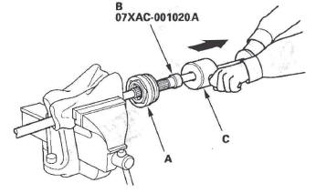
6. Remove the outboard joint (A) using the threaded adapter (B) and a commercially available 5/8"-18 UNF slide hammer (C).
7. Remove the driveshaft from the bench vise.
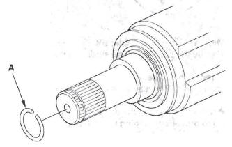
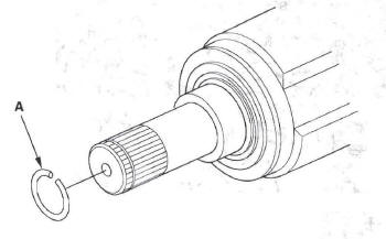
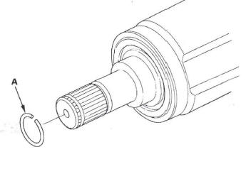
8. Remove the stop ring (A) from the driveshaft.
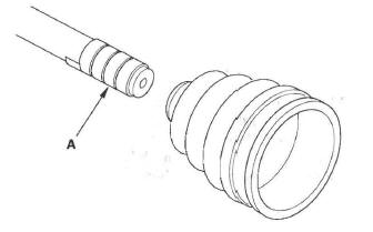
9. Wrap the splines on the driveshaft with vinyl tape (A) to prevent damaging the boot.
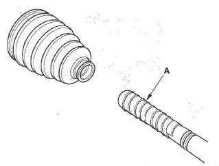
10. Remove the outboard boot. Be careful not to damage the boot.
11. Remove the vinyl tape.
Rear Driveshaft Reassembly
Exploded View
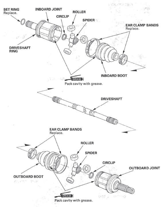
Japan-built Models
Exploded View
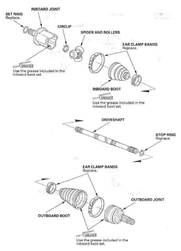
US-built Models
Special Tools Required
Inner handle, 30 mm 07946-MB00000
NOTE: Refer to the Exploded View as needed during this procedure.
Inboard Joint Side (Japan-built Models)
1. Wrap the splines with vinyl tape (A) to prevent damaging the inboard boot.
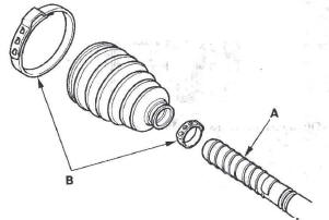
2. Install the new ear clamp bands (B) and inboard boot, then remove the vinyl tape. Be careful not to damage the inboard boot.
3. Install the spider (A) onto the driveshaft by aligning the marks (B) you made on the spider and the end of the driveshaft.
4. Fit the circlip (C) into the driveshaft groove. Always rotate the circlip in its groove to make sure it is fully seated.
5. Fit the rollers (A) onto the spider (B) with their high shoulders facing outward, and note these items:
- Reinstall the rollers in their original positions on the spider by aligning the marks (C) you made.
- Hold the driveshaft pointed up to prevent the rollers from falling off.
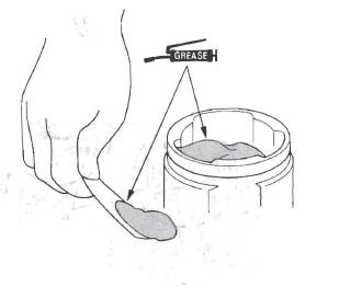
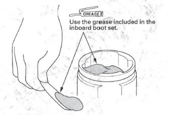
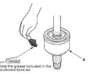
6. Pack the inboard joint with the joint grease included in the new inboard boot set.
Grease quantity
Inboard joint: 80-90 g (2.8-3.2 oz)
7. Fit the inboard joint (A) onto the driveshaft, and note these items:
- Reinstall the inboard joint onto the driveshaft by aligning the marks (B) on you made the inboard joint and the rollers (C).
- Hold the driveshaft so the inboard joint points up to prevent it from falling off.
8. Fit the boot (A) ends onto the driveshaft (B) and inboard joint (C).
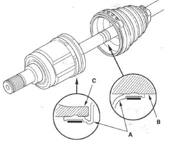
9. Adjust the length of the drives hafts to the figure as shown, then adjust the boots to halfway between full compression and full extension. Make sure the ends of the boots seat in the grooves of the driveshaft and joint. Doing this prevents a vacuum or too much air in the boot, preventing it from compressing or extending properly.
Inboard joint: 146.9-150.9 mm (5.8-5.9 in.)
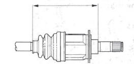
Outboard joint: 136.9-140.9 mm (5.4-5.5 in.)
10. Make sure the ends of the boot are seated in the grooves in the driveshaft and joint. then install the boot bands.
11. Install the new set ring (A).
Inboard Joint Side (US-built Models)
1. Wrap the splines with vinyl tape (A) to prevent damaging the inboard boot.
2. Install the new ear clamp bands (B) and inboard boot, then remove the vinyl tape. Be careful not to damage the inboard boot.
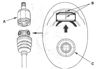
3. Install the spider and rollers (A) onto the driveshaft by aligning the marks (B) you made, install it using the inner handle (D).
4. Install the circlip (C) into the drives haft groove.
Rotate the circlip in its groove to make sure it is fully seated.
5. Pack the inboard joint with the joint grease included in the new inboard boot set.
Grease quantity
Inboard joint: 96-124 g (3.4-4.3 oz)
6. Fit the inboard joint onto the driveshaft, and note these items:
- Reinstall the inboard joint onto the driveshaft by aligning the marks (A) you made, on the inboard joint and the rollers.
- Hold the driveshaft so the inboard joint is pointing up to prevent it from falling off.
7. Fit the boot ends onto the driveshaft and the inboard joint, then install the new boot band onto the boot.
8. Repeat step 8 for the band on the other end of the boot.
Outboard Joint Side
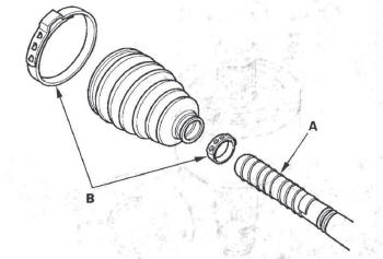
1. Wrap the splines with vinyl tape (A) to prevent damaging the outboard boot.
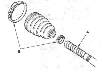
2. Install the new ear clamp bands (B) and outboard boot, then remove the vinyl tape. Be careful not to damage the outboard boot.
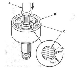
3. Install the new stop ring (A) into the driveshaft groove (B).
4. Pack about half of the grease included in the new joint boot set into the driveshaft hole in the outboard joint. Insert the driveshaft (A) into the outboard joint (B) until the stop ring (C) is closed.
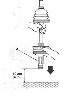
5. To completely seat the outboard joint, pick up the driveshaft and joint, and tap or hit them from a height of about 10 cm (4 in.) onto a hard surface. Do not use a hammer as excessive force may damage the driveshaft. Be careful not to damage the threaded section (A) of the outboard joint.
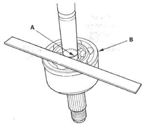
6. Check the alignment of the paint mark (A) you made with the outboard joint end (B).
7. Pack the outboard joint (A) with the remaining joint grease included in the new outboad boot set.
Grease quantity
Outboard joint: 70-90 g (2.5-3.2 oz)
8. Fit the boot ends (A) into the drives haft (B) and outboard joint (C) grooves.
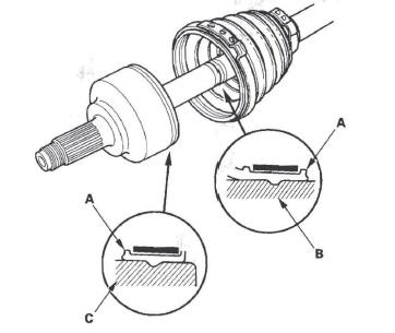
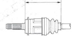
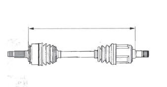
9. Adjust the length of the driveshafts to the figure as shown, then adjust the boots to halfway between full compression and full extension. Make sure the ends of the boots seat in the groove of the driveshaft and joint. Doing this prevents a vacuum or too much air in the boot, preventing it from compressing or extending properly.
Left drives haft: 647-652 mm (25.5-25.7 in.)
Right driveshaft: 698-703 mm (27.5-27.7 in.)
10. Install the new ear clamp band onto the boot.
11. Repeat step 10 for the band on the other end of the boot.
Rear Driveshaft Installation
NOTE: Before starting installation, make sure the mating surfaces of the joint and the splined section are free from dirt or dust.
1. Install the outboard joint (A) into the rear hub (B).
NOTE: Be careful not to damage the ABS wheel sensor (C).
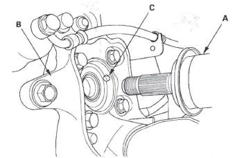
2. Install the rear driveshafts into the rear differential assembly (see step 3 ).
3. Apply a small amount of engine oil to the seating surface of the new spindle nut (A).
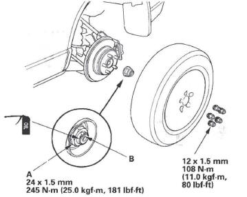
4. Install a new spindle nut, then tighten the nut. After tightening, use a drift to stake the spindle nut shoulder (B) against the driveshaft.
5. Clean the mating surfaces of the brake disc and the rear wheel, then install the rear wheel with the wheel nuts.
6. Turn the rear wheel by hand, and make sure there is no interference between the driveshaft and surrounding parts.
7. Refill the differential fluid.
READ NEXT:
 Propeller Shaft
Propeller Shaft Inspection
Universal Joint and Boots
1. Set the parking brake, then shift the transmission to
the N position.
2. Raise the vehicle on a lift.
3. Check the center support bearing (A)
Steering
Special Tools
Piston Seal Ring Sizing Tool
Bushing Base
Piston Seal Ring Guide
Cylinder End Seal Slide
Locknut Wrench, 40 mm
Ball Joint Remover, 28 mm
Valve Seal Ring Sizing Tool
Sleeve Sea
Symptom Troubleshooting
Hard Steering
1. Check the power assist.
Is the initial turning load more than 34 N (3.5 kgf,
7.7 Ibf) ?
YES-Go to step 2.
NO-Power assist is OK.
2. Connect the P/S joint adapter (pump), P/S joint
SEE MORE:
DTC Troubleshooting
DTC indicator 1: An Open in the Air Mix
Control Motor Circuit
1. Start the engine.
2. Turn on the A/C, then set the temperature control
dial to Max Hot.
3. Turn the ignition switch OFF and then ON (II).
4. Do the self-diagnostic with the HVAC control unit.
5. Check for DTCs.
Is DTC 1 indicated?
Adjusting the Sound
You can adjust the sound on the
navigation screen. To adjust the
sound, push the AUDIO button, then
enter the sound grid by touching the
SOUNDicon on the display.
BASS - Adjusts the bass.
TREBLE - Adjusts the treble. To
adjust the treble and bass, touch
either
or
on the tr
