Honda CR-V: Symptom Troubleshooting
Hard Steering
1. Check the power assist.
Is the initial turning load more than 34 N (3.5 kgf, 7.7 Ibf) ? YES-Go to step 2.
NO-Power assist is OK.
2. Connect the P/S joint adapter (pump), P/S joint adapter (hose), and P/S pressure gauge T/N 07406- 0010001 (see page 17-9), T/N 07406-001000A or T/N 07406-001A101 (see page 17-10) to the pump.
3. Measure steady-state fluid pressure from the pump ' at idle.
Is the pressure 1,470 kPa (15 kgf/cm2, 213 psi) or less? YES-Go to step 4.
NO-Go to step 8.
4. Measure the pump relief pressure at idle.
Is the pressure 7,350- 8,050 kPa (75- 82 kgf/cm2, 1,070- 1,170 psi) or more? YES-Go to step 5.
NO-Go to step 9.
5. With a spring scale, measure the power assist in both directions, to the left and to the right.
Are the two measurements within 5.0 N (0.51 kgf, 1.12 lbf) of each other? YES-Go to step 6.
NO-Go to step 11.
6. Measure the fluid pressure with both pressure gauge valves open (if so equipped), while turning the steering wheel fully to the left and fully to the right.
Is the pressure 7,350- 8,050 kPa (75- 82 kgf/cm2, 1,070- 1,170 psi) or more? YES-Go to step 7.
NO-Faulty steering gearbox.
7. Adjust the rack guide (see page 17-31), and retest.
Is the steering OK? YES-Repair is completed.
NO-Faulty steering gearbox.
8. Check the outlet and return hoses and lines between the pump and the steering gearbox for clogging and deformation.
Are the lines clogged or deformed? YES-Repair or replace the lines.
NO-Faulty valve body unit.
9. Disassemble the pump.
10. Check the pressure control valve for smooth movement and leaks (see step 16).
Is the pressure control valve OK? YES-Faulty pump assembly.
NO-Faulty pressure control valve.
11. Check the cylinder lines for deformation.
Are any of the lines deformed? YES-Replace the deformed line.
NO-Go to step 12.
12. Check for a bent rack shaft or misadjusted rack guide (too tight).
Is the rack shaft bent or the rack guide adjusted too tight? YES-Replace the rack shaft, or readjust the rack guide.
NO-Faulty valve body unit.
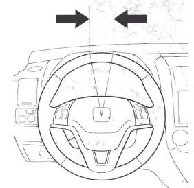
Steering Wheel Rotational Play Check
1. Turn the front wheels to the straight ahead position.
2. Measure how far you can turn the steering wheel left and right without moving the front wheels.
- If the play is within the limit, the steering gearbox and linkages are OK.
- If the play exceeds the limit, adjust the rack guide. If the play is still excessive after rack guide adjustment, inspect the steering linkage and steering gearbox.
Rotational play: 0-10 mm (0-0.39 in.)
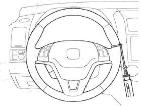
Power Assist Check
NOTE: This test should be done with original equipment tires and wheels at the correct tire pressure.
1. Check the power steering fluid level.
2. Start the engine, let it idle, and turn the steering wheel from lock-to-lock several times to warm up the fluid.
3. Attach a commercially available spring scale to the steering wheel. With the engine idling and the vehicle on a clean, dry floor, pull the scale as shown and read it as soon as the tires begin to turn.
- If the scale reads no more than the specification, the steering gearbox and pump are OK.
- If the scale reads more than the specification, troubleshoot the steering system.
Initial turning load: 34 N (3.5 kgt, 7.7 Ibt)
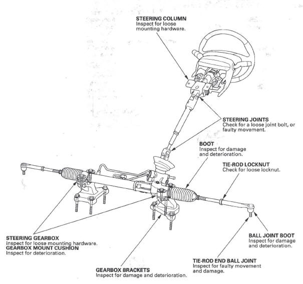
Steering Linkage and Gearbox Inspection
READ NEXT:
 Pump Pressure Test
Pump Pressure Test with T/N 07406-0010001
Special Tools Required
P/S joint adapter (pump) 07ZAK-S7C0100
P/S joint adapter (hose) 07ZAK-S7C0200
P/S pressure gauge 07406-0010001
Check the fluid pre
Pump
Pump Replacement
1. Place a suitable container under the vehicle.
2. Drain the power steering fluid from the reservoir.
3. Remove the drive belt (A) from the pump pulley.
4. Cover the auto-tensione
Steering Wheel
Steering Wheel Removal
SRS components are located in this area. Review the SRS component locations and the
precautions and procedures before
doing repairs or service.
1. Make sure you have the anti-t
SEE MORE:
Using a Booster Seat
A child who has outgrown a forwardfacing
child seat should ride in a
back seat and use a booster seat
until the lap/shoulder belt fits them
properly without the booster.
Some states, Canadian provinces and
territories also require children to
use a booster seat until they reach a
Brake Hose
Brake Hose and Line Inspection
1. Inspect the brake hoses for damage, deterioration, leaks, interference,
and twisting.
2. Check the brake lines for damage, rusting, and leaks. Also check for bent
brake lines.
3. Check for leaks at hose and line joints and connections, and retighten if
necess
