Honda CR-V: CD, DVD, and PC Card Removal/Installation
If the display will not open, use this procedure to manually open the display and remove the CD, DVD, and/or the PC card.
1. Remove the navigation unit from the vehicle.
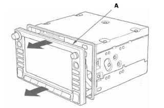
2. On the bench, carefully pull the display (A) straight out (about 1/2 inch).
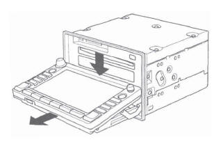
3. Fold down the display as shown in the diagram below.
4. Push the PC card ,eject button (A) to eject the customer's PC card (if installed). Power is not required for this function.
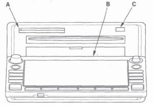
5. Open the plastic cover (B) for the navigation DVD slot. Do not remove the plastic cover.
6. With the display open, temporarily reconnect the unit in the dash (to power it up).
7. Push the CD "eject" button (C), and navigation DVD "eject" button and remove the discs (holding both discs by their edges to avoid fingerprints). To avoid scratches, place the navigation DVD, and customer's CD in a jewel case if available.
8. Close the plastic cover that covers the navigation DVD slot.
9. Close the display by first returning the display to the upward position, and then pushing the entire display straight back into the unit.
10. After installing the new navigation unit, re-insert the navigation DVD, the customer's CD, and PC card.
READ NEXT:
 Navigation Unit Removal/Installation
SRS components are located in this area. Review the SRS component location.
Also review the precautions and procedures in the SRS section before doing repairs or
service.
NOTE:
Put on gloves to pro
Seat Belts
Component Location Index
REAR CENTER SEAT BELT
REAR CENTER SEAT BELT BUCKLE and
LEFT REAR SEAT BELT BUCKLE
REAR SEAT BELT
FRONT SEAT BELT
FRONT SEAT BELT BUCKLES
RIGHT FRONT SEAT BELT LOWER A
SEE MORE:
Text Data Display Function
Each time you press the TITLE
button, the display shows you the
text, if the disc was recorded with
text data.
You can see the album, artist, and
track name in the display. If a disc is
recorded in MP3 or WMA, you can
see the folder and file name, and the
artist, album, and track tag.
Emergency Towing
If your vehicle needs to be towed,
call a professional towing service or
organization. Never tow your vehicle
with just a rope or chain. It is very
dangerous.
On 4WD models
The only way you can safely tow
your vehicle is with flat-bed
equipment. The operator will load
Any other metho
