Honda CR-V: PGM-FI System
Honda CR-V (2006–2011) Service Manual / Fuel and Emissions / PGM-FI System
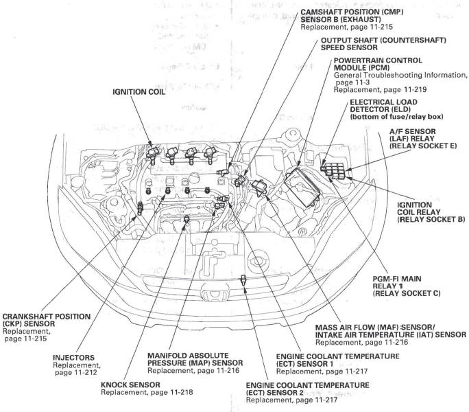
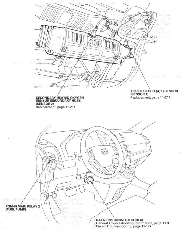
Component Location Index
-
CAMSHAFT POSITION (CMP) SENSOR B (EXHAUST)
-
OUTPUT SHAFT (COUNTERSHAFT) SPEED SENSOR
-
POWERTRAIN CONTROL MODULE (PCM)
-
ELECTRICAL LOAD DETECTOR (ELD) (bottom of fuse/relay box)
-
A/F SENSOR (LAF) RELAY (RELAY SOCKET E)
-
IGNITION COIL RELAY (RELAY SOCKET B)
-
MASS AIR FLOW (MAF) SENSOR/INTAKE AIR TEMPERATURE (IAT) SENSOR
-
ENGINE COOLANT TEMPERATURE (ECT) SENSOR 1
-
ENGINE COOLANT TEMPERATURE (ECT) SENSOR 2
-
MANIFOLD ABSOLUTE PRESSURE (MAP) SENSOR
-
KNOCK SENSOR
-
INJECTORS
-
CRANKSHAFT POSITION (CKP) SENSOR
-
IGNITION COIL
-
DATA LINK CONNECTOR (DLC)
-
PGM-FI MAIN RELAY 2 (FUEL PUMP)
- DTC Troubleshooting
- F-CAN Circuit Troubleshooting
- DLC Circuit Troubleshooting
- Injector Replacement
- PCM Replacement
READ NEXT:
 DTC P0101: MAF Sensor Range/Performance Problem
NOTE:
Before you troubleshoot, record all freeze data and
any on-board snapshot, and review the general
troubleshooting information.
If DTC P1128, P1129, P2228, and/or P2229 are stored
at the sa
DTC P0111: IAT Sensor Circuit Range/Performance Problem
NOTE: Before you troubleshoot, record all freeze data
and any on-board snapshot, and review the general
troubleshooting information.
1. Check for poor connections or loose terminals at
ECT sensor 1/2
SEE MORE:
Mirrors
Keep the inside and outside mirrors
clean and adjusted for best visibility.
Be sure to adjust the mirrors before
you start driving.
The inside mirror has day and night
positions. The night position reduces
glare from headlights behind you.
Flip the tab on the bottom edge of
the mirr
Rear Differential Fluid Inspection and
Replacement
1. With the vehicle on level ground, inspect the
differential fluid with the ignition switch turned to
LOCK (0).
2. Use solvent and a brush to wash off any oil and dirt
from the differential fluid inspection oil filler plug.
3. Remove the oil filler plug (A) and the sealing
washer (B), then check
© 2016-2026 Copyright www.hcrv.net
