Honda CR-V: F-CAN Circuit Troubleshooting
NOTE: Information marked with an asterisk (*) applies to the CANL line.
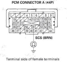
1. Turn the ignition switch OFF.
2. Jump the SCS line with the HDS.
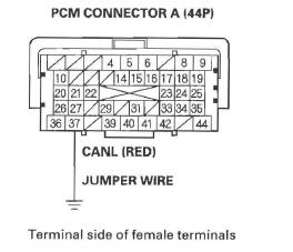
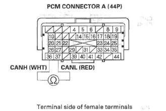
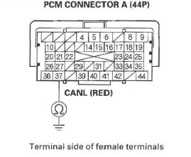
3. Disconnect PCM connector A (44P), then disconnect the HDS.
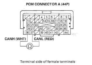
4. Measure resistance between PCM connector terminals A36 and A37.
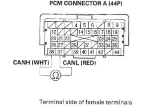
Is there about 95- 116 Ω ? YES-Go to step 33.
NO-Go to step 5.
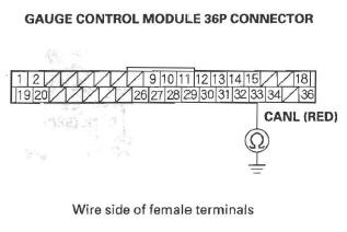
5. Disconnect the gauge control module 36P connector.
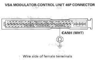
6. Disconnect the VSA modulator-control unit 46P connector, and the yaw rate/lateral acceleration sensor 4P connector.
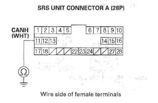
7. Disconnect SRS unit connector A (28P) (see step 9).
8. Disconnect the TPMS unit 20P connector.
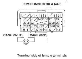
9. Check for continuity between PCM connector terminals A36 and A37.
Is there continuity? YES-Repair short in the wires between PCM connector terminals A36 and A37.
NO-Go to step 10.
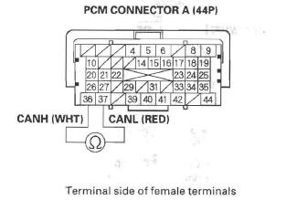
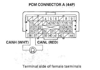
10. Connect PCM connector terminal A36 to body ground with a jumper wire.
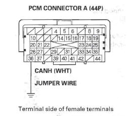
11. Check for continuity between gauge control module 36P connector terminal No. 34 and body ground.
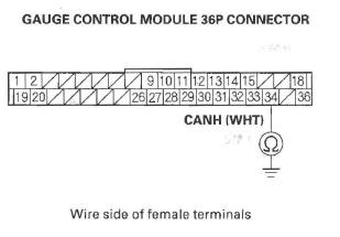
Is there continuity? YES-Go to step 12.
NO-Repair open in the wire between the PCM (A36) and the gauge control module.
12. Check for continuity between VSA modulator-control unit 46P connector terminal No. 39 and body ground.
Is there continuity? YES-Go to step 13.
NO-Repair open in the wire between the PCM (A36) and the VSA modulator-control unit.
13. Check for continuity between SRS unit connector A (28P) terminal No. 11 and body ground.
Is there continuity? YES-Go to step 14.
NO-Repair open in the wire between the PCM (A36) and the SRS unit.
14. Remove the jumper wire from PCM connector A (44P).
15. Connect PCM connector terminal A37 to body ground with a jumper wire.
16. Check for continuity between gauge control module 36P connector terminal No. 33 and body ground.
Is there continuity? YES-Go to step 17.
NO-Repair open in the wire between the PCM (A37) and the gauge control module.
17. Check for continuity between VSA modulator-control unit 46P connector terminal No. 38 and body ground.
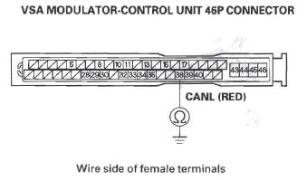
Is there continuity? YES-Go to step 18.
NO-Repair open in the wire between the PCM (A37) and the VSA modulator-control unit.
18. Check for continuity between SRS unit connector A (28P) terminal No. 12 and body ground.
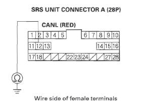
Is there continuity? YES-Go to step 19.
NO-Repair open in the wire between the PCM (A37) and the SRS unit.
19. Reconnect the gauge control module 36P connector.
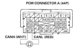
20. Measure resistance between PCM connector terminals A36 and A37.
Is there about 108- 132 Ω ? YES-Go to step 21.
NO-Substitute a known-good gauge control module. If the HDS identifies the vehicle, replace the original gauge control module.
21. Disconnect the gauge control module 36P connector.
22. Reconnect the VSA modulator-control unit 46P connector.
23. Measure resistance between PCM connector terminals A36 and A37.
Is there about 2.34- 2.86 k Ω ? YES-Go to step 24.
NO-Substitute a known-good VSA modulator-control unit. If the HDS identifies the vehicle, replace the original VSA modulator-control unit.
24. Disconnect the VSA modulator-control unit 46P connector.
25. Reconnect the yaw rate/lateral acceleration sensor 4P connector.
26. Measure resistance between PCM connector terminals A36 and A37.
Is there about 2.34- 2.86 k Ω ? YES-Go to step 27.
NO-Substitute a known-good yaw rate/lateral acceleration sensor. If the HDS identifies the vehicle, replace the original yaw rate/ lateral acceleration sensor.
27. Disconnect the yaw rate/lateral acceleration connector.
28. Reconnect SRS unit connector A (28P).
29. Measure resistance between PCM connector terminals A36 and A37.
Is there about 2.34- 2.86 k Ω ? YES-Go to step 30.
NO-Substitute a known-good SRS unit. If the HDS identifies the vehicle, replace the original SRS unit.
30. Disconnect SRS unit connector A (28P).
31. Reconnect the TPMS unit 20P connector.
32. Measure resistance between PCM connector terminals A36 and A37.
Is there about 2.34- 2.86 k Ω ? YES-Update the PCM if it does not have the latest software, or substitute a known-good PCM, then recheck. If the symptom/indication goes away with a known-good PCM, replace the original PCM.
NO-Substitute a known-good TPMS unit. If the HDS identifies the vehicle, replace the original TPMS unit.
33. Disconnect the gauge control module 36P connector.
34. Disconnect the VSA modulator-control unit 46P connector, and the yaw rate/lateral acceleration sensor 4P connector.
35. Disconnect SRS unit connector A (28P) (see step 9 ).
36. Disconnect the TPMS unit 20P connector.
37. Check for continuity between PCM connector terminal A36 and body ground.
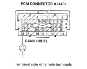
Is there continuity? YES-Repair short in the wire between the PCM connector terminal A36 and the gauge control module, the VSA modulator-control unit, the yaw late/lateral acceleration sensor, the SRS unit, the TPMS unit or the DLC.
NO-Go to step 38.
38. Check for continuity between PCM connector terminal A37 and body ground.
Is there continuity? YES-Repair short in the wire between PCM connector terminal A37 and the gauge control module, the VSA modulator-control unit, the yaw rate/lateral acceleration sensor, the SRS unit, the TPMS unit, or the DLC.
NO-Go to step 39.
39. Reconnect all connectors.
40. Connect the HDS to the DLC.
41. Disconnect the gauge control module 36P connector.
42. Turn the ignition switch ON (II), and read the HDS.
Does the HDS identify the vehicle? YES-Replace the gauge control module.
NO-Go to step 43.
43. Turn the ignition switch OFF.
44. Reconnect the gauge control module 36P connector.
45. Disconnect the VSA modulator-control unit 46P connector.
46. Turn the ignition switch ON (II), and read the HDS.
Does the HDS identify the vehicle? YES-Replace the VSA modulator-control unit.
NO-Go to step 47.
47. Turn the ignition switch OFF.
48. Reconnect the VSA modulator-control unit 46P connector.
49. Disconnect the yaw rate/lateral acceleration sensor 4P connector.
50. Turn the ignition switch ON (II), and read the HDS.
Does the HDS identify the vehicle? YES-Replace the yaw rate/lateral acceleration sensor.
NO-Go to step 51.
51. Turn the ignition switch OFF.
52. Reconnect the yaw rate/lateral acceleration sensor 4P connector.
53. Disconnect SRS unit connector A (28P).
54. Turn the ignition switch ON (II), and read the HDS.
Does the HDS identify the vehicle? YES-Replace the SRS unit.
NO-Go to step 55.
55. Turn the ignition switch OFF.
56. Reconnect SRS unit connector A (28P).
57. Disconnect the TPMS unit 20P connector.
58. Turn the ignition switch ON (II), and read the HDS.
Does the HDS identify the vehicle? YES-Replace the TPMS unit.
NO-Update the PCM if it does not have the latest software, or substitute a known-good PCM, then recheck. If the symptom/indication goes away with a known-good PCM, replace the original PCM.
MIL Circuit Troubleshooting
1. Turn the ignition switch ON (II).
2. Do the gauge self-diagnostic function.
Does the MIL indicator flash? YES-Go to step 3.
NO-Substitute a known-good gauge control module, and recheck. If the MIL circuit is OK, replace the original gauge control module.
3. Connect the HDS to the DLC.
4. Check the SCS in the DATA LIST with the HDS.
Is a short indicated? YES-Go to step 5.
NO-Update the PCM if it does not have the latest software, or substitute a known-good PCM, then recheck. If the symptom/indication goes away with a known-good PCM, replace the original PCM.
5. Turn the ignition switch OFF.
6. Disconnect PCM connector A (44P), then disconnect the HDS.
7. Check for continuity between PCM connector terminal A31 and body ground.
Is there continuity? YES-Repair short in the wire between the PCM (A31) and the SRS unit, the DLC.
NO-Update the PCM if it does not have the latest software, or substitute a known-good PCM, then recheck. If the symptom/indication goes away with a known-good PCM, replace the original PCM.
READ NEXT:
 DLC Circuit Troubleshooting
NOTE: Make sure the HDS and the DLC cable of the
HDS is not defective.
1. Turn the ignition switch OFF.
2. Connect the HDS to the DLC.
NOTE: Make sure the HDS is properly connected to
the DLC.
3. T
Injector Replacement
1. Relieve fuel pressure.
2. Remove the engine cover.
3. Disconnect the connectors (A) from the injectors.
4. Remove the ground cable bolt (G101) (B).
5. Disconnect the quick-connect fitting (C).
PCM Replacement
NOTE:
Make sure the HDS is loaded with the latest software
version.
If you are replacing the PCM after substituting a
known-good PCM, reinstall the original PCM, then do
this procedure.
During
SEE MORE:
Wiper Blades
Check the condition of the wiper
blades at least every six months.
Replace them if you find signs of
cracking in the rubber, areas that are
getting hard, or if they leave streaks
and unwiped areas when used.
To replace a front wiper blade:
1. Raise each wiper arm off the
windshield, l
Alternator Removal and
Installation
Removal
1. Make sure you have the anti-theft code for the
audio system and the navigation system (if
equipped), then write down the XM radio presets.
2. Disconnect the negative cable from the battery first,
then disconnect the positive cable.
3. Remove the drive belt.
4. Remove the drive belt aut
