Honda CR-V: Injector Replacement
1. Relieve fuel pressure.
2. Remove the engine cover.
3. Disconnect the connectors (A) from the injectors.
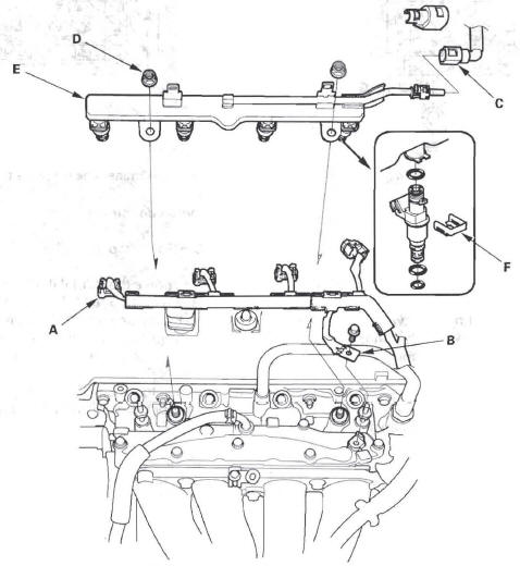
4. Remove the ground cable bolt (G101) (B).
5. Disconnect the quick-connect fitting (C).
6. Remove the fuel rail mounting nuts (D) from the fuel rail (E).
7. Remove the injector clip (F) from the injector.
8. Remove the injector from the fuel rail.
9. Coat the new O-rings (A) with clean engine oil, and insert the injectors (B) into the fuel rail (C).
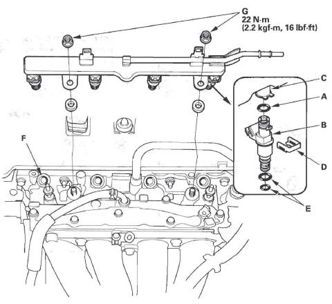
10. Install the injector clip (D).
11. Coat the injector O-rings (E) with clean engine oil.
12. Install the fuel rail and the injectors in the injector base (F).
13. Install the fuel rail mounting nuts (G) and the ground cable bolt (G101).
14. Connect the injector connectors.
15. Connect the quick-connect fitting.
16. Turn the ignition switch ON (II), but do not operate the starter. After the fuel pump runs for about 2 seconds, the fuel rail will be pressurized. Repeat this two or three times, then check for fuel leakage.
A/F Sensor Replacement
Special Tools Required
O2 sensor wrench, Snap-on S3176, or equivalent, commercially available
1. Disconnect the A/F sensor 4P connector (A), then remove the A/F sensor (B).
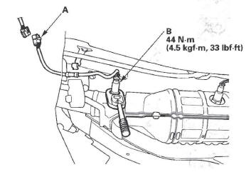
2. Install the parts in the reverse order of removal.
Secondary HO2S Replacement
Special Tools Required
O2 sensor wrench, Snap-on S3176, or equivalent, commercially available.
1. Disconnect the secondary HO2S 4P connector (A), then remove the secondary HO2S (B).
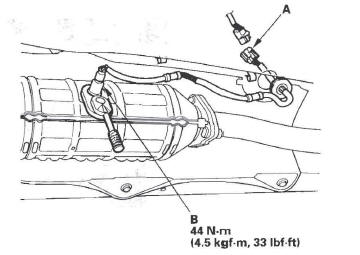
2. Install the parts in the reverse order of removal.
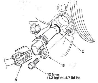
CMP Sensor B Replacement
1. Remove the EGR valve.
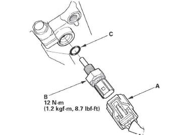
2. Disconnect the CMP sensor B connector (A).
3. Remove CMP sensor B (B).
4. Install the parts in the reverse order of removal with a new O-ring (C).
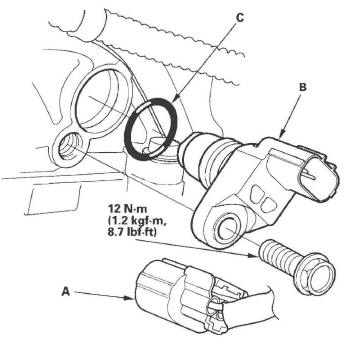
CKP Sensor Replacement
1. Disconnect the CKP sensor connector (A).
2. Remove the CKP sensor (B).
3. Install the parts in the reverse order of removal with a new O-ring (C).
4. Do the CKP pattern clear/CKP pattern learn procedure with the HDS.
MAP Sensor Replacement
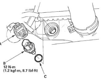
1. Disconnect the MAP sensor connector (A).
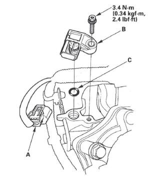
2. Remove the MAP sensor (B).
3. Install the parts in the reverse order of removal with a new O-ring (C).
MAF Sensor/IAT Sensor Replacement
1. Disconnect the MAF sensor/IAT sensor connector (A).
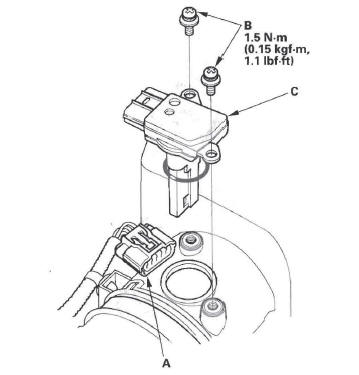
2. Remove the screws (B).
3. Remove the MAF sensor/IAT sensor (C).
4. Install the parts in the reverse order of removal with a new O-ring (D).
ECT Sensor 1 Replacement
1. Drain the engine coolant.
2. Remove the air cleaner.
3. Disconnect the ECT sensor 1 connector (A).
4. Remove ECT sensor 1 (B).
5. Install the parts in the reverse order of removal with a new O-ring (C), then refill the radiator with engine coolant.
ECT Sensor 2 Replacement
1. Remove the splash shield.
2. Drain the engine coolant.
3. Disconnect the ECT sensor 2 connector (A), then remove ECT sensor 2 (B).
4. Install ECT sensor 2 with a new O-ring (C).
5. Install the splash shield.
6. Refill the radiator with engine coolant.
Knock Sensor Replacement
1. Lift the vehicle, and support it with jackstands.
2. Disconnect the knock sensor connector (A).
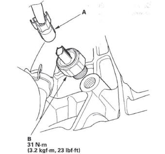
3. Remove the knock sensor (B).
4. Install the parts in the reverse order of removal.
READ NEXT:
 PCM Replacement
NOTE:
Make sure the HDS is loaded with the latest software
version.
If you are replacing the PCM after substituting a
known-good PCM, reinstall the original PCM, then do
this procedure.
During
Electronic Throttle Control System
Component Location Index
ELECTRONIC THROTTLE
CONTROL SYSTEM (ETCS)
CONTROL RELAY
(RELAY SOCKET F)
POWERTRAIN CONTROL
MODULE (PCM)
General Troubleshooting
Information
Replacemen
SEE MORE:
General Operation
The automatic transmission is a combination of a 3-element torque converter
and triple-shaft electronically controlled
unit which provides 5 speeds forward and 1 reverse. The entire unit is
positioned in line with the engine.
Torque Converter, Gears, and Clutches
The torque converter consists of a
DTC P0457: EVAP System Leak Detected/Fuel
Fill Cap Loose or Missing
NOTE: Before you troubleshoot, record all freeze data and any on-board
snapshot, and review the general troubleshooting information.
1. Check the fuel fill cap (the cap must say "Tighten to
click"). It should turn 1/4 turn after it's tight, then it
clicks.
Is the correct fuel fill cap installed a
