Honda CR-V: VSA (Vehicle Stability Assist) System Components
Honda CR-V (2006–2011) Service Manual / Brakes / VSA (Vehicle Stability Assist) System Components
Component Location Index
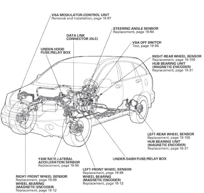
- VSA MODULATOR-CONTROL UNIT
- Removal and Installation
- UNDER-HOOD FUSE/RELAY BOX
- DATA LINK CONNECTOR (DLC)
- STEERING ANGLE SENSOR
- Replacement
- VSA OFF SWITCH
- Test
- RIGHT-REAR WHEEL SENSOR
- Replacement
- HUB BEARING UNIT
(MAGNETIC ENCODER)
- Replacement
- LEFT-REAR WHEEL SENSOR
- Replacement
- HUB BEARING UNIT
(MAGNETIC ENCODER)
- Replacement
- UNDER-DASH FUSE/RELAY BOX
- LEFT-FRONT WHEEL SENSOR
- Replacement
- WHEEL BEARING
(MAGNETIC ENCODER)
- Replacement
- YAW RATE-LATERAL
ACCELERATION SENSOR
- Replacement
- RIGHT-FRONT WHEEL SENSOR
- Replacement
- WHEEL BEARING
(MAGNETIC ENCODER)
- Replacement
- General Troubleshooting Information
- System Description
- DTC Troubleshooting
- Symptom Troubleshooting
- Steering Angle Sensor Replacement
READ NEXT:
 General Troubleshooting Information
System Indicator
This system has four indicators:
ABS indicator (A)
Brake system indicator (B)
VSA indicator (C)
VSA activation indicator (D)
When the system detects a problem, it will turn the
System Description
VSA Modulator-control Unit Inputs and Outputs for 46P Connector
System Outline
This system is composed of the VSA modulator-control unit, the wheel sensors,
the steering angle sensor, and the
yaw
SEE MORE:
Steering Angle Sensor Replacement
NOTE: Do not damage or drop the combination switch as the steering angle
sensor is sensitive to shock and vibration.
1. Remove the steering wheel.
2. Remove the steering column covers and the cable reel.
3. Remove the combination switch assembly.
4. Remove the combination light switch (A) and t
Removing a Disc
To remove a disc from the audio unit,
fold back the screen by pressing the
OPEN button. Press
the disc eject button (
) to
remove the disc. If you eject the disc,
but do not remove it from the slot,
the system will automatically reload
it after 10 seconds and put it in pause
mode.
© 2016-2026 Copyright www.hcrv.net
