Honda CR-V: Symptom Troubleshooting
VSA activation indicator does not go off, and no DTCs are stored
1. Turn the ignition switch ON (II), and watch the VSA activation indicator.
Does VSA activation indicator go off within 2 seconds? YES-The system is OK at this time.
NO-Go to step 2.
2. Turn the ignition switch OFF.
3. Disconnect the VSA OFF switch 5P connector.
4. Check the VSA OFF switch.
Is the VSA OFF switch OK? YES-Go to step 5.
NO-Replace the VSA OFF switch.
5. Remove the gauge control module.
6. Disconnect gauge control module connector B (36P).
7. Check for continuity between VSA OFF switch 5P connector terminal No.2 and body ground.
Is there continuity? YES-Repair short to body ground between the gauge control module and the VSA OFF switch.
NO-Substitute a known-good gauge control module, then go to step 1 and recheck. If it is OK, replace the original gauge control module.
ABS indicator, brake system indicator, and VSA indicator do not go off at the same time
1. Turn the ignition switch OFF.
2. Check the No.4 (7.5 A) fuse in the under-dash fusel relay box.
Is the fuse blown? YES-Install a new No.4 (7.5 A) fuse, and recheck.
NO-Reinstall the checked fuse, then go to step 3.
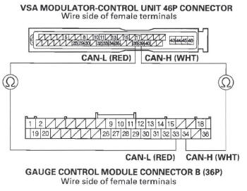
3. Disconnect the VSA modulator-control unit 46P connector.
4. Turn the ignition switch ON (II).
5. Measure the voltage between VSA modulator-control unit 46P connector terminal No. 40 and body ground.
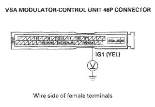
Is there battery voltage? YES-Go to step 6.
NO- Repair open in the wire between the No.4 (7.5 A) fuse in the under-dash fuse/relay box and the VSA modulator-control unit.
6. Turn the ignition switch OFF.
7. Check for continuity between VSA modulator-control unit 46P connector terminal No. 43 and body ground.
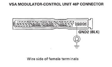
Is there continuity? YES-Go to step 8.
NO-Repair open in the wire between the VSA modulator-control unit and body ground (G202).
8. Disconnect gauge control module connector B (36P).
9. Check for continuity between the appropriate VSA modulator-control unit 46P connector terminals and gauge control module connector B (36P) terminals respectively (see table).
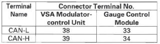
Is there continuity? YES-Check for loose terminals in the VSA modulator-control unit 46P connector. Check for a loose connection at G202. If necessary, substitute a known-good VSA modulator-control unit and retest.
NO-Repair open in the wire between the gauge control module and the VSA modulator-control unit.
READ NEXT:
 Steering Angle Sensor Replacement
NOTE: Do not damage or drop the combination switch as the steering angle
sensor is sensitive to shock and vibration.
1. Remove the steering wheel.
2. Remove the steering column covers and the cable
Doors
Component Location Index-Front Door
DOOR CENTER OUTER TRIM
DOOR LINING BRACKETS
DOOR OUTER MOLDING
Replacement
DOOR GLASS OUTER
WEATHERSTRIP
Replacement
HINGE
DOOR CHECKER
DOOR
SEE MORE:
To Remove Exterior Frost or Ice Fromthe Windows
1. Select
. The system
automatically switches to fresh air
mode and turns on the A/C.
The A/C indicator does not come
on if it was off to start with.
2. Select
.
3. Set the fan and temperature
controls to maximum level.
To clear the windows faster, you can
close the dashboard corner
To Play a CD
To play CDs, the ignition switch
must be in the ACCESSORY (I) or
ON (II) position.
You operate the CD changer with
the same controls used for the indash
disc player or the radio. To
select the CD changer, touch the
CDC icon. The disc and track
numbers are displayed. The system
will
