Honda CR-V: Steering Angle Sensor Replacement
NOTE: Do not damage or drop the combination switch as the steering angle sensor is sensitive to shock and vibration.
1. Remove the steering wheel.
2. Remove the steering column covers and the cable reel.
3. Remove the combination switch assembly.
4. Remove the combination light switch (A) and the wiper/washer switch (B).
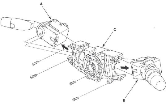
5. Replace the combination switch body (C).
6. Install the combination switch in the reverse order of removal.
NOTE:
- Do not remove the steering angle sensor from the combination switch body.
- When installing the cable reel , set the turn signal canceling sleeve position.
Yaw Rate-Lateral Acceleration Sensor Replacement
NOTE:
- Do not damage or drop the sensor as it is sensitive.
- Do not use air or electric impact tools.
1. Turn the ignition switch OFF.
2. Remove both sides of the center lower cover.
3. Disconnect the yaw rate-lateral acceleration sensor 4P connector (A).
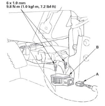
4. Remove the sensor mounting bolts, and remove the yaw rate-lateral acceleration sensor (B).
5. Install in the reverse order of removal.
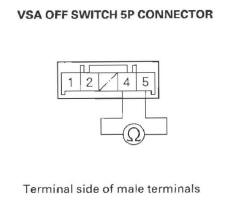
VSA Off Switch Test
1. Turn the ignition switch OFF.
2. Remove the power mirror switch (A), then disconnect the VSA OFF switch 5P connector (B).
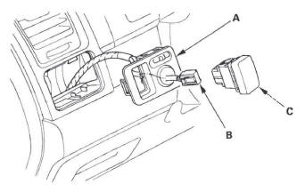
3. Push out the VSA OFF switch (C) from the back of the switch panel.
4. Check for continuity between the VSA OFF switch 5P connector terminal No.1 and No. 2. There should be continuity when the switch is pressed, and no continuity when the switch is released.
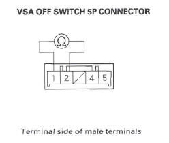
5. Check for continuity between the VSA OFF switch 5P connector terminal No.4 and No.5. There should be continuity at all times.
VSA Modulator-Control Unit Removal and Installation
NOTE:
- Do not spill brake fluid on the vehicle; it may damage the paint; if brake fluid gets on the paint. wash it off immediately with water.
- Be careful not to damage or deform the brake lines during removal and installation.
- To prevent the brake fluid from flowing, plug and cover the hose ends and joints with a shop towel or equivalent material.
Removal
1. Turn the ignition switch OFF.
2. Disconnect the VSA modulator-control unit 46P connector (A) by pulling up the lock (B); the connector disconnects itself.
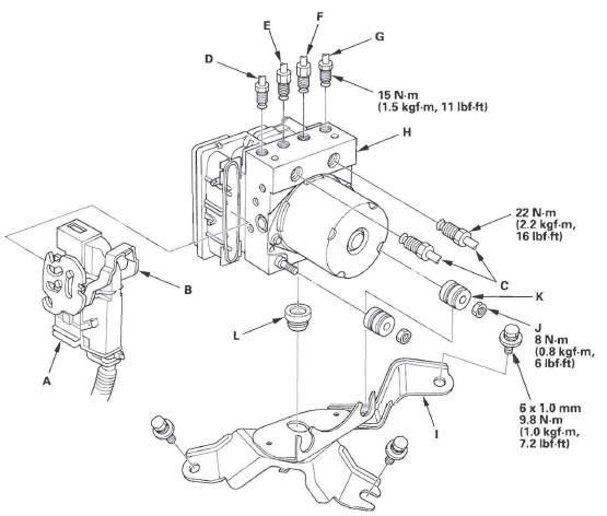
3. Disconnect the six brake lines from the VSA modulator-control unit.
NOTE: Brake lines are connected to the master cylinder (C) and to the right-front (D), the left-rear (E), the right-rear (F), and the left-front (G) brake systems.
4. Remove the VSA modulator-control unit (H) with the bracket (I) from the body.
5. Remove the locknuts (J), then remove the VSA modulator-control unit from the bracket.
NOTE: During installation, install a new bushing (K) and new grommet (L). Otherwise, unwanted noise and vibration may be transmitted to the vehicle.
Installation
1. Install the new bushing and new grommets. (Otherwise, unwanted noise and vibration may be transmitted to the vehicle.) 2. Install the VSA modulator-control unit on the bracket, then install new locknuts.
3. Install the bracket with the VSA modulator-control unit.
4. Reconnect the six brake lines, then tighten the flare nuts with the specified torque.
5. Align the connecting surface of the VSA modulator-control unit 46P connector to the VSA modulator-control unit.
6. Lower the lock of the VSA modulator-control unit 46P connector, then confirm the connector is fully seated.
7. Bleed the brake system.
8. Start the engine, and check that the ABS and the VSA indicators go off.
9. Test-drive the vehicle, and check that the ABS and VSA indicators do not come on.
NOTE: If the brake pedal is spongy, there may be air trapped in the modulator and then induced into the normal brake system during modulation. Bleed the brake system again.
Wheel Sensor Replacement
Front
1. Turn the ignition switch OFF.
2. Release the connector holding clamps (A), then disconnect the wheel sensor connector (B).
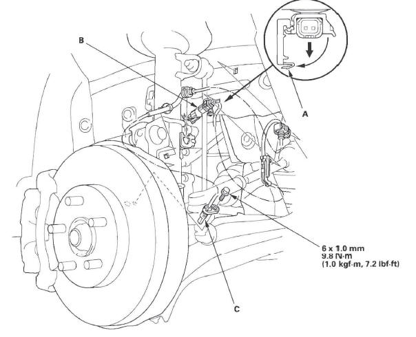
3. Remove the clips, the bolt and the wheel sensor (C).
4. Install the wheel sensor in the reverse order of removal, and note these items:
- Install the sensor carefully to avoid twisting the wires.
- If the wheel sensor comes in contact with the wheel bearing, it is faulty.
5. Start the engine, and check that the ABS and the VSA indicators go off.
6. Test-drive the vehicle, and check that the ABS and the VSA indicators do not come on.
Rear
1. Turn the ignition switch OFF.
2. Release the connector holding clamps (A), then disconnect the wheel sensor connector (B).
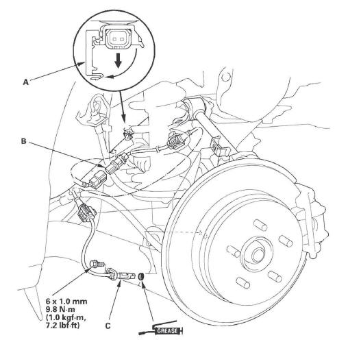
3. Remove the clips, the bolt and the wheel sensor (C).
4. Install the wheel sensor in the reverse order of removal, and note these items:
- Apply multipurpose grease to the O-ring (C).
- Install the sensor carefully to avoid twisting the wires.
- If the wheel sensor comes in contact with the hub bearing unit, it is faulty.
5. Start the engine, and check that the ABS and the VSA indicators go off.
6. Test-drive the vehicle, and check that the ABS and the VSA indicators do not come on.
READ NEXT:
 Doors
Doors
Component Location Index-Front Door
DOOR CENTER OUTER TRIM
DOOR LINING BRACKETS
DOOR OUTER MOLDING
Replacement
DOOR GLASS OUTER
WEATHERSTRIP
Replacement
HINGE
DOOR CHECKER
DOOR
Front Door
Front Door Panel Removal/Installation
Special Tools Required
KTC trim tool set SOJATP2014 *
Trim pad remover, Snap-on A 177 A or equivalent,
commercially available
* Available through the Ameri
SEE MORE:
A/T Gear Position Indicator
Component Location Index
A/T GEAR POSITION INDICATOR
F-CAN Communication Circuit Troubleshooting
Gauge Control Module Self-diagnostic Function Indicator Drive Circuit
Check
Communication Line Check
A/T GEAR POSITION INDICATOR PANEL LIGHT HARNESSReplacement
A/T GEAR POSITION INDICATOR PANEL
Mirrors
Component Location Index
POWER MIRROR ACTUATOR
Replacement
POWER MIRROR
Replacement
MIRROR HOLDER
Replacement
MOUNT
REARVIEW MIRROR
Replacement
Power Mirror Replacement
Special Tools Required
KTC trim tool set SOJATP2014 *
* Available through the American Honda T
