Honda CR-V: CKP Pulse Plate Replacement
1. Remove the front wheels.
2. Remove the splash shield (see step 21).
3. Remove the drive belt.
4. Remove the cylinder head cover.
5. Set the No.1 piston at top dead center (TDC). The punch mark on the variable valve timing control (VTC) actuator and the punch mark on the exhaust camshaft sprocket should be at the top. Align the TDC marks on the VTC actuator and exhaust camshaft sprocket (see step 5).
6. Disconnect the crankshaft position (CKP) sensor connector and VTC oil control solenoid valve connector (see step 6).
7. Remove the VTC oil control solenoid valve.
8. Remove the crankshaft pulley.
9. Support the engine with a jack and a wood block under the oil pan.
10. Remove the upper torque rod (see step 10).
11. Remove the ground cable, then remove the side engine mount bracket (see step 11).
12. Remove the side engine mount bracket mounting bolts (see step 12).
13. Remove the cam chain case and side engine mount bracket (see step 13).
14. Remove the CKP pulse plate.
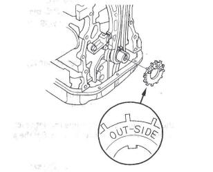
15. Install the CKP pulse plate.
16. Check the chain case oil seal for damage. lf the oil seal is damaged, replace the chain case oil seal.
17. Remove all of the old liquid gasket from the chain case mating surfaces, bolts, and bolt holes.
18. Clean and dry the chain case mating surfaces.
19. Apply liquid gasket, P/N 08717-0004, 08718-0001, 08718-0003, or 08718-0009, evenly to the engine block mating surface of the chain case. Install the component within 5 minutes of applying the liquid gasket (see step 15).
NOTE:
- If you apply liquid gasket P/N 08718-0012, the component must be installed within 4 minutes.
- If too much time has passed after applying the liquid gasket, remove the old liquid gasket and residue, then reapply new liquid gasket.
20. Apply liquid gasket to the engine block upper surface contact areas on the chain case and lower block upper surface contact areas on the chain case (see step 16).
21. Apply liquid gasket, P/N 08717-0004, 08718-0001 , 08718-0003, or 08718-0009, evenly to the oil pan mating surface of the chain case. Install the component within 5 minutes of applying the liquid gasket (see step 17).
NOTE:
- If you apply liquid gasket P/N 08718-0012, the component must be installed within 4 minutes.
- If too much time has passed after applying the liquid gasket, remove the old liquid gasket and residue, then reapply new liquid gasket.
22. Install the new O-ring, side engine mount bracket, and mounting bolts on the chain case. Set the edge of the chain case to the edge of the oil pan, then install the chain case on the engine block (see step 18). Wipe off the excess liquid gasket on the oil pan and chain case mating area.
NOTE:
- When installing the chain case, do not slide the bottom surface onto the oil pan mounting surface.
- Wait at least 30 minutes before filling the engine with oil.
- Do not run the engine for at least 3 hours after installing the chain case.
23. Tighten the side engine mount bracket mounting bolts (see step 19).
24. Install the side engine mount bracket, then loosely tighten the new bolt and nut, and loosely tighten the bolt. Install the ground cable (see step 20).
25. Remove the air cleaner housing assembly.
26. Loosen the transmission mounting bolt and nuts (see step 23).
27. Raise the lift to full height.
28. Loosen the lower torque rod mounting bolt (see step 25).
29. Lower the vehicle on the lift.
30. Tighten the side engine mount mounting bolts and nut (see step 27).
31. Tighten the transmission mounting bolt and nuts (see step 28).
32. Raise the lift to full height.
33. Tighten the lower torque rod mounting bolt (see step 30).
34. Lower the vehicle on the lift.
35. Install the air cleaner housing assembly.
36. Install the upper torque rod, then tighten the new upper torque rod mounting bolts in the numbered sequence shown (see step 33).
37. Install the VTC oil control solenoid valve.
38. Connect the CKP sensor connector and VTC oil control solenoid valve connector (see step 36).
39. Install the crankshaft pulley.
40. Install the cylinder head cover.
41. Install the drive belt.
42. Do the CKP pattern clear/CKP learn procedure.
READ NEXT:
 Cylinder Head Cover Removal/Installation
Cylinder Head Cover Removal
1. Remove the intake manifold cover.
2. Remove the four ignition coils.
3. Disconnect the evaporative emission (EVAP)
canister purge valve connector.
4. Remove the dipst
Cylinder Head Removal
NOTE:
Use fender covers to avoid damaging painted
surfaces.
To avoid damage, unplug the wiring connectors
carefully while holding the connector portion.
To avoid damaging the cylinder head, wait
VTC Actuator, Exhaust Camshaft Sprocket
Replacement
Removal
1. Remove the cam chain.
2. Hold the camshaft with an open-end wrench, then
loosen the variable valve timing control (VTC)
actuator mounting bolt and exhaust camshaft
sprocket mounting bolt.
SEE MORE:
To Load a Disc
The in-dash disc player is behind the
navigation screen. To use the disc
player, press the OPEN button
beside the screen. The screen folds
back, and the disc slot appears.
Insert a disc about halfway into the
disc slot. The drive will pull the disc
in the rest of the way and beg
How to Set Readiness Codes
Malfunction Indicator Lamp (MIL) Indication
(In relation to Readiness Codes)
The vehicle has certain "readiness codes" that are part
of the on-board diagnostics for the emissions systems.
If the vehicle's battery has been disconnected or gone
dead, if the DTCs have been cleared, or if the PCM has
b
