Honda CR-V: Cylinder Head Removal
NOTE:
- Use fender covers to avoid damaging painted surfaces.
- To avoid damage, unplug the wiring connectors carefully while holding the connector portion.
- To avoid damaging the cylinder head, wait until the engine coolant temperature drops below 100 ºF (38 ºC) before loosening the cylinder head bolts.
- Mark all wiring and hoses to avoid misconnection.
Also, be sure that they do not contact other wiring or hoses, or interfere with other parts.
1. Relieve fuel pressure.
2. Drain the engine coolant.
3. Remove the air cleaner housing.
4. Remove the drive belt.
5. Remove the intake manifold.
6. Remove the exhaust manifold.
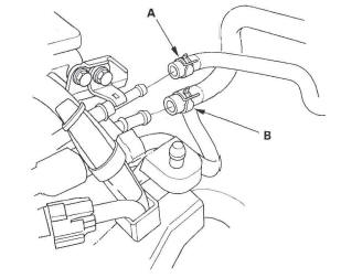
7. Remove the evaporative emission (EVAP) canister hose (A) and brake booster vacuum hose (B).
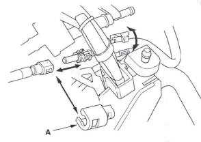
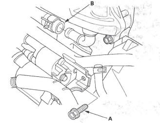
8. Remove the quick-connect fitting cover (A), then disconnect the fuel feed hose.
9. Remove the positive crankcase ventilation (PCV) hose (A) and ground cable (B).
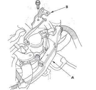
10. Remove the harness holder (A) from the bracket, then remove the harness holder bracket (B).
11. Remove the upper radiator hose (A) and heater hoses (B).
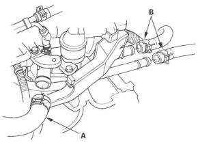
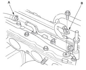
12. Remove the bolt (A) securing the connecting pipe.
13. Remove the water bypass hose (B).
14. Remove the engine wire harness connectors and wire harness clamps from the cylinder head.
- Four fuel injector connectors
- Engine coolant temperature (ECT) sensor 1 connector
- Camshaft position (CMP) sensor A (Intake) connector
- Camshaft position (CMP) sensor B (Exhaust) connector
- Rocker arm oil control solenoid connector
- Rocker arm oil pressure switch connector
- EVAP canister purge valve connector
- Exhaust gas recirculation (EGR) valve connector
15. Remove the cam chain.
16. Remove the rocker arm assembly.
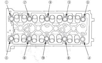
17. Remove the cylinder head bolts. To prevent warpage, unscrew the bolts in sequence 1/3 turn at a time; repeat the sequence until all bolts are loosened.
18. Remove the cylinder head.
CMP Pulse Plate A Replacement
1. Remove the cylinder head cover.
2. Remove camshaft position (CMP) sensor A.
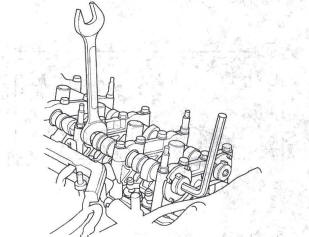
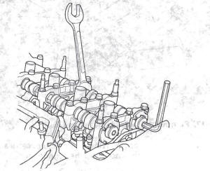
3. Hold the camshaft with an open-end wrench, then loosen the bolt.
4. Remove CMP pulse plate A.
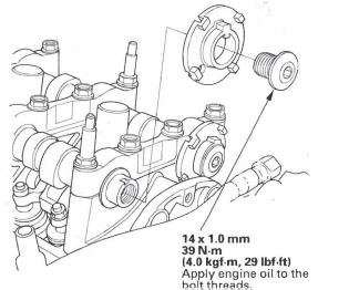
5. Install CMP pulse plate A in the reverse order of removal.
CMP Pulse Plate B Replacement
1. Remove the cylinder head cover.
2. Remove camshaft position (CMP) sensor B.
3. Hold the camshaft with an open-end wrench, then loosen the bolt.
4. Remove CMP pulse plate B.
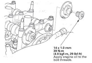
5. Install CMP pulse plate B in the reverse order of removal.
READ NEXT:
 VTC Actuator, Exhaust Camshaft Sprocket
Replacement
VTC Actuator, Exhaust Camshaft Sprocket
Replacement
Removal
1. Remove the cam chain.
2. Hold the camshaft with an open-end wrench, then
loosen the variable valve timing control (VTC)
actuator mounting bolt and exhaust camshaft
sprocket mounting bolt.
Camshaft Inspection
NOTE: Do not rotate the camshaft during inspection.
1. Remove the rocker arm assembly.
2. Put the rocker shaft holders, camshaft, and
camshaft holders on the cylinder head, then tighten
the bolts, i
Valve, Spring, and Valve Seal Removal
Special Tools Required
Valve spring compressor attachment 07757-PJ1010A
Identify the valves and valve springs as they are
removed so that each item can be reinstalled in its
original position.
1. Rem
SEE MORE:
Accessories
Your dealer has Honda accessories
that allow you to personalize your
vehicle. These accessories have
been designed and approved for your
vehicle, and are covered by warranty.
Although non-Honda accessories
may fit on your vehicle, they may not
meet factory specifications, and
could ad
Cable Reel Replacement
Removal
1. Make sure the front wheels are aligned straight
ahead.
2. Disconnect the negative cable from the battery, and
wait at least 3 minutes.
3. Remove the driver's airbag.
4. Disconnect the connector (A) from the cable reel,
then remove the steering wheel bolt (B).
5. Confirm that the front
