Honda CR-V: Cylinder Head Cover Removal/Installation
Cylinder Head Cover Removal
1. Remove the intake manifold cover.
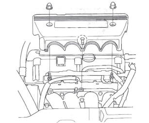
2. Remove the four ignition coils.
3. Disconnect the evaporative emission (EVAP) canister purge valve connector.
4. Remove the dipstick (A), the breather hose (B), and power steering (P/S) hose clamp (C).
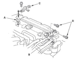
5. Remove two bolts (D) securing the EVAP canister purge valve bracket.
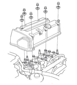
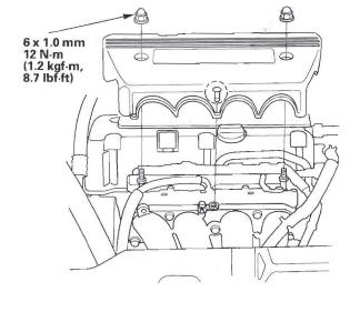
6. Remove the cylinder head cover.
Cylinder Head Cover Installation
1. Thoroughly clean the head cover gasket and the groove.
2. Install the head cover gasket (A) in the groove of the cylinder head cover (B).
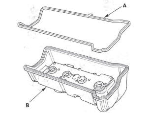
3. Check that the mating surfaces are clean and dry.
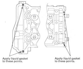
4. Apply liquid gasket, P/N 08717-0004,08718-0001, 08718-0003, or 08718-0009, on the chain case and the No. 5 rocker shaft holder mating areas. Install the component within 5 minutes of applying the liquid gasket.
NOTE:
- If you apply liquid gasket P/N 08718-0012, the component must be installed within 4 minutes.
- If too much time has passed after applying the liquid gasket, remove the old liquid gasket and residue, then reapply new liquid gasket.
5. Set the spark plug seals (A) on the spark plug tubes.
Place the cylinder head cover (B) on the cylinder head, then slide the cover slightly back and forth to seat the head cover gasket.
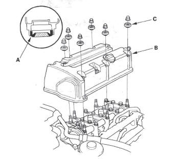
6. Inspect the cover washers (C). Replace any washer that is damaged or deteriorated.
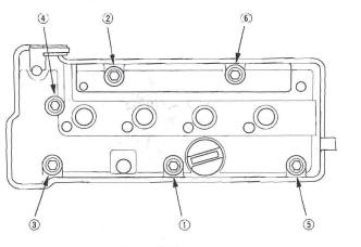
7. Tighten the bolts in two or three steps. In the final step tighten all bolts, in sequence, to 12 N*m (1.2 kgf*m, 8.7 Ibf*ft).
NOTE:
- Wait at least 30 minutes before filling the engine with oil.
- Do not run the engine for at least 3 hours after installing the head cover.
8. Install two bolts (A) securing the evaporative emission (EVAP) canister purge valve bracket.
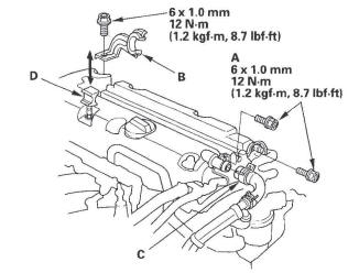
9. Install the power steering (P/S) hose clamp (B), breather hose (C), and the dipstick (D).
10. Connect the EVAP canister purge valve connector.
11. Install the four ignition coils.
12. Install the intake manifold cover.
READ NEXT:
 Cylinder Head Removal
NOTE:
Use fender covers to avoid damaging painted
surfaces.
To avoid damage, unplug the wiring connectors
carefully while holding the connector portion.
To avoid damaging the cylinder head, wait
VTC Actuator, Exhaust Camshaft Sprocket
Replacement
Removal
1. Remove the cam chain.
2. Hold the camshaft with an open-end wrench, then
loosen the variable valve timing control (VTC)
actuator mounting bolt and exhaust camshaft
sprocket mounting bolt.
Camshaft Inspection
NOTE: Do not rotate the camshaft during inspection.
1. Remove the rocker arm assembly.
2. Put the rocker shaft holders, camshaft, and
camshaft holders on the cylinder head, then tighten
the bolts, i
SEE MORE:
Recirculation Control Motor
Circuit Troubleshooting
1. Check the No. 36 (10 A) fuse in the under-dash fuse/
relay box.
Is the fuse OK?
YES-Go to step 2.
NO-Replace the fuse, and recheck. If the fuse blows again, check for a short in
the No. 36 (10 A) fuse circuit.
2. Disconnect the recirculation control motor 7P
connector.
3. Turn the ignition s
DTC P0451: FTP Sensor Range/Performance
Problem
NOTE:
Before you troubleshoot, record all freeze data and any on-board
snapshot, and review the general troubleshooting information.
If DTC P2422 is stored at the same time as DTC P0451,
troubleshoot DTC P2422 first, then recheck for DTC
P0451.
1. Turn the ignition switch ON (II).
2. Clear
