Honda CR-V: Turn Signal/Hazard Flasher
Component Location Index
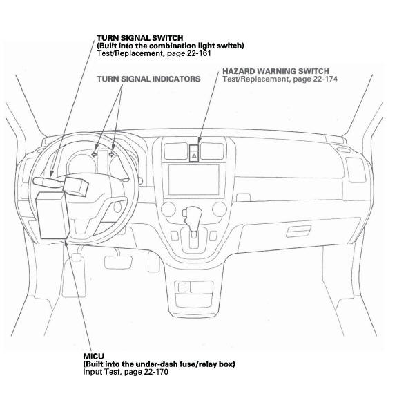
- TURN SIGNAL SWITCH (Built into the combination light switch)
- TURN SIGNAL INDICATORS
- HAZARD WARNING SWITCH
- MICU (Built into the under-dash fuse/relay box)
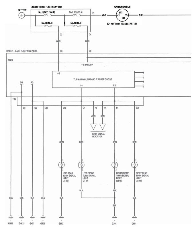
Circuit Diagram

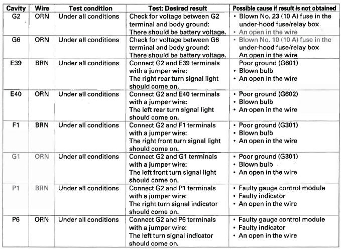
MICU Input Test
NOTE: Before testing, troubleshoot the B-CAN System Diagnosis Test Mode A.
1. Check the No. 10 (7.5 A) fuse in the under-dash fuse/relay box. lf the fuse is blown, replace it and go to step 2.
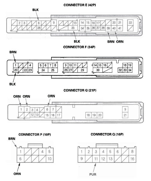
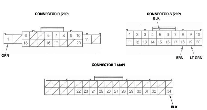
2. Disconnect the under-dash fuse/relay box connectors E, F, G, P, Q, R, S, and T.
NOTE: All connector views are wire side of female terminals.
3. Inspect the connector and socket terminals to be sure they are all making good contact.
- If the terminals are bent, loose or corroded, repair them as necessary and recheck the system.
- If the terminals look OK, go to step 4.
4. With the connectors still disconnected, make these input tests at the appropriate connector.
- If any test indicates a problem, find and correct the cause, then recheck the system.
- If all the input tests prove OK, go to step 5.
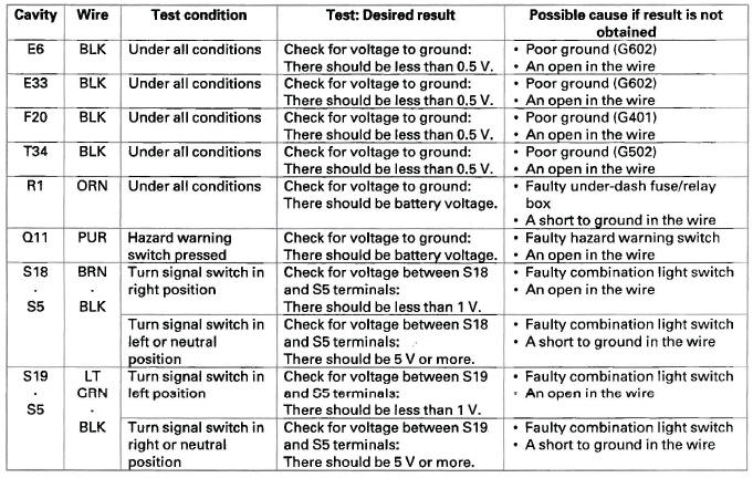
5. Reconnect the connectors to the under-dash fuse/relay box, and make these input tests at the connectors.
- If any test indicates a problem, find and correct the cause, then recheck the system.
- If all the input tests prove OK, the MICU must be faulty; replace the under-dash fuse/relay box.
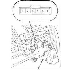
Hazard Warning Switch Test/Replacement
1. Remove the center vent.
2. Remove the hazard warning switch (A).
3. Check for continuity between the terminals in each switch position according to the table.
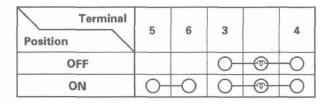
4. If the continuity is not as specified, replace the hazard warning switch.
READ NEXT:
 Interior Lights
Component Location Index
With moon roof
INDIVIDUAL MAP LIGHTS
INTERIOR LIGHT SWITCH
(Built into the moonroof switch)
AMBIENT LIGHT
(Built into the moonroof switch)
CEILING LIGHT
CARGO AREA LI
Entry Lights Control System
Component Location Index
With moonroof
INDIVIDUAL MAP LIGHTS
IGNITION KEY SWITCH
IGNITION KEY LIGHT
CEILING LIGHT
CARGO AREA LIGHT
RIGHT REAR DOOR SWITCH
FRONT PASSENGER'S
DOOR SWITCH
LEFT
Power Windows
Component Location Index
POWER WINDOW MASTER SWITCH
(With built-in control unit)
FRONT PASSENGER'S POWER WINDOW SWITCH
FRONT PASSENGER'S POWER WINDOW MOTOR
RIGHT REAR POWER WINDOW SWITCH
RIGHT
SEE MORE:
Using a Track List
You can also select a track/file
directly from a track list on the audio
display. Press the AUDIO button to
show the audio display, then touch
the Track List icon. The track list
menu appears on the display.
When playing a CD recorded with
text data, each track name is shown
on th
DTC P0335: CKP Sensor No Signal
NOTE: Before you troubleshoot, record all freeze data and any on-board
snapshot, and review the general troubleshooting information.
1. Turn the ignition switch ON (II).
2. Clear the DTC with the HDS.
3. Start the engine.
4. Check for Temporary DTCs or DTCs with the HDS.
Is DTC P0335 indicated
