Honda CR-V: Entry Lights Control System
Component Location Index
With moonroof
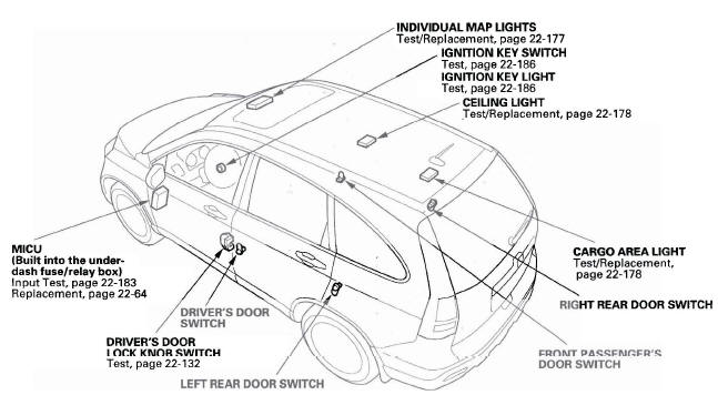
- INDIVIDUAL MAP LIGHTS
- IGNITION KEY SWITCH
- IGNITION KEY LIGHT
- CEILING LIGHT
- CARGO AREA LIGHT
- RIGHT REAR DOOR SWITCH
- FRONT PASSENGER'S DOOR SWITCH
- LEFT REAR DOOR SWITCH
- DRIVER'S DOOR SWITCH
- DRIVER'S DOOR LOCK KNOB SWITCH
- MICU (Built into the under-dash fuse/relay box)
Without moonroof
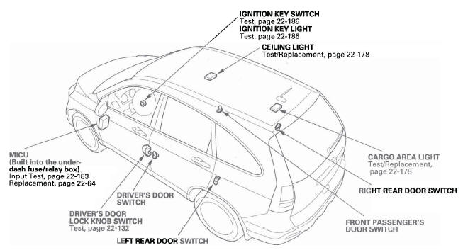
- IGNITION KEY SWITCH
- IGNITION KEY LIGHT
- CEILING LIGHT
- CARGO AREA LIGHT
- FRONT PASSENGER'S DOOR SWITCH
- LEFT REAR DOOR SWITCH
- DRIVER'S DOOR SWITCH
- DRIVER'S DOOR LOCK KNOB SWITCH
- MICU (Built into the under-dash fuse/relay box)
Circuit Diagram
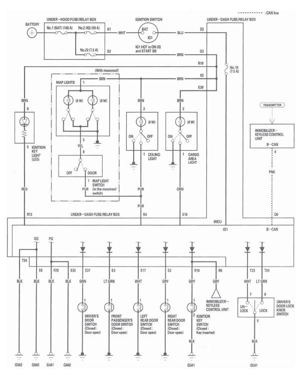
MICU Input Test
NOTE: Before testing, troubleshoot the B-CAN System Diagnosis Test Mode A.
1. Check the No. 10 (7.5 A) fuse in the under-dash fuse/relay box. If the fuse is blown, replace it and go to step 2.
2. Disconnect the under-dash fuse/relay box connectors E, F, K, Q, R, and T.
NOTE: All connector views are wire side of female terminals.
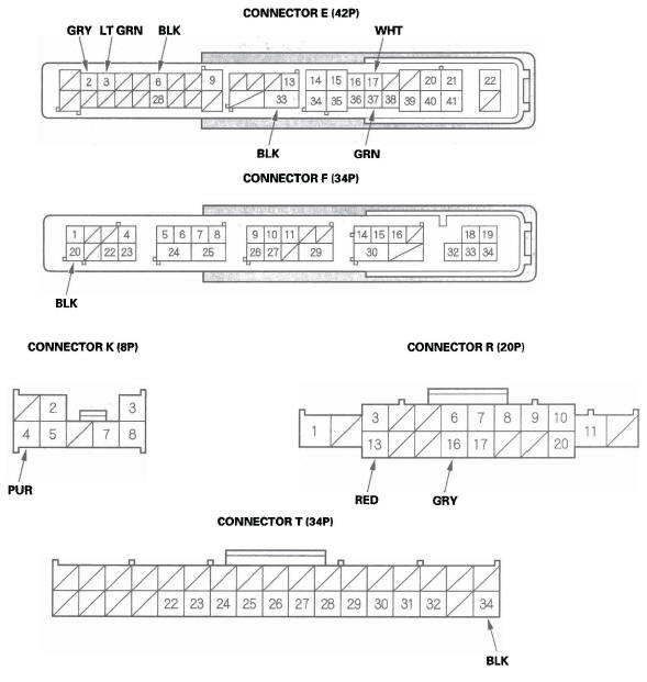
3. Inspect the connector and socket terminals to be sure they are all making good contact.
- If the terminals are bent, loose or corroded, repair them as necessary and recheck the system.
- If the terminals look OK, go to step 4.
4. With the connectors still disconnected, do these input tests at the appropriate connector.
- If any test indicates a problem, find and correct the cause, then recheck the system.
- If all the input tests prove OK, go to step 5.
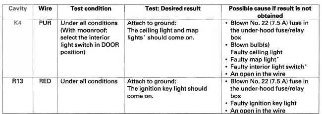
*: With moon roof
5. Reconnect the connectors to the under-dash fuse/relay box, and do these input tests at the connectors.
- If any test indicates a problem, find and correct the cause, then recheck the system.
- If all the input tests prove OK, the MICU must be faulty; replace the under-dash fuse/relay box.

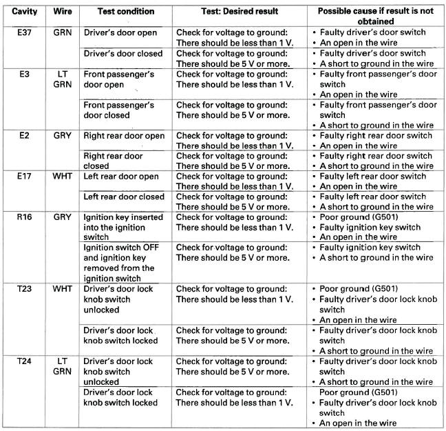
Ignition Key Switch Test
1. Remove the steering column upper and lower covers.
2. Disconnect the 6P connector (A).
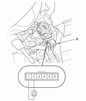
3. Check for continuity between the No.1 and No.2 terminals.
- There should be continuity with the key in the ignition switch.
- There should be no continuity with the key removed.
4. If the continuity is not as specified, replace the ignition switch.
Ignition Key Light Test
1. Remove the steering column upper and lower covers.
2. Disconnect the 6P connector (A).
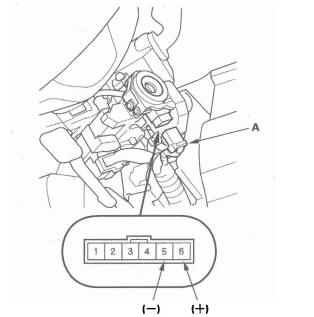
3. The LED should come on when power is connected to the No.6 terminal and ground is connected to No.5 terminal.
4. If the LED does not come on, replace the ignition switch.

