Honda CR-V: Troubleshooting
Troubleshooting - B-CAN System Diagnosis Test Mode A
Check the PCM for DTCs, and troubleshoot PCM or F-CAN loss of communication errors first, then do this diagnosis if the symptom is related to the B-CAN system.
NOTE: Always cycle the ignition switch within 3 seconds when prompted in the DTC troubleshooting procedures in this section.
1. Compare the symptom with this list of B-CAN related systems:
- Gauge control module
- Exterior lights
- Turn signals
- Entry light control
- Interior lights
- Door-open and tailgate-open indicators
- Horns (security and panic)
- Chimes (key-in, seat belt, lights-on, and parking brake)
- Power window/moon roof timer
- Wiper/washer
- Security
- Keyless entry
- Power door locks
- Key interlock
Dash light brightness control - Tailgate release actuator
Is the symptom related to the B-CAN system? YES-Go to step 2.
NO-Go to the system troubleshooting for the system with the symptom.
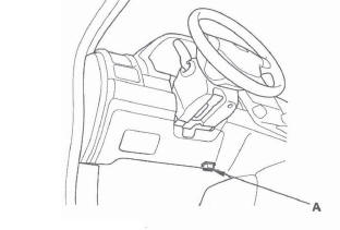
2. Connect the HDS to the data link connector (A), then turn the ignition switch ON (II).
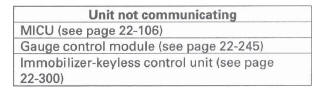
3. From the BODY ELECTRICAL system select menu, select UNIT INFORMATION, and then select CONNECTED UNIT to see if the following control units are communicating with the HDS.
MICU
- Gauge control module Immobilizer-keyless control unit
NOTE:
- If a unit is communicating with the HDS, DETECT will be displayed.
- If a unit is not communicating or the vehicle is not equipped, "Not Available" will be displayed.
Are all control units communicating with the HDS? YES-Go to step 4.
NO-If any of the control units are not communicating, go to B-CAN System Diagnosis Test Mode B. If all units are not communicating or only the MICU is communicating, go to DTC B1000 troubleshooting.
4. Select the system that has the problem from the BODY ELECTRICAL system select menu, then select DTCs.
Are any DTCs indicated? YES-Go to step 5.
NO-If the problem is related to one of the following items, go to B-CAN System Diagnosis Test Mode C if the system does not stop or turn off. Go to Test Mode D if the system does not run or turn on.
- Exterior lights
- Turn signals
- Entry light control
- Interior lights
- Horn (security and panic)
- Wiper/washer
If the problem is related to one of the following items, go to the troubleshooting for that individual system.
- Gauge control module
- Door-open and tailgate-open indicator
- Chimes (key-in, seat belt, lights-on, and parking brake)
- Security
- Keyless entry
- Key interlock
- Dash light brightness control
- Audio system
- Navigation (if equipped)
5. Record all DTCs, and sort them by DTC type.
6. Troubleshoot the DTC(s) in this order:
- Battery voltage DTCs.
- Internal error DTCs.
- Loss of communication DTCs. Begin troubleshooting with the lowest number first (Example: if DTC B1008 and B1011 are retrieved, begin by troubleshooting B1008).
- Signal error DTCs.
Troubleshooting - B-CAN System Diagnosis Test Mode B
Do this diagnosis if any of the control units a re not communicating (Not Available is displayed in the HDS) as found by the B-CAN System Diagnosis Test Mode A.
1. Using the HDS, select the system that has the symptom from the BODY ELECTRICAL system select menu.
2. Select DTCs, and then check for loss of communication DTCs.
Are any loss of communication DTCs indicated? YES-Go to step 3.
NO-Replace the MICU.
3. Do the input test for the unit not communicating with the HDS.
Troubleshooting - B-CAN System Diagnosis Test Mode C
Do this diagnosis if a component that is controlled by the B-CAN system does not stop or turn off.
NOTE:
- If the component does not turn on, go to B-CAN System Diagnosis Test Mode D.
- See the B-CAN system unit input/output index for a list of input and output devices and the control units that monitor the input and controls the output devices.
- Always cycle the ignition switch within 3 seconds when prompted in the DTC troubleshooting procedures in this section.
1. Check for DTCs by selecting the TEST MODE menu from the HDS.
Are any DTCs indicated? YES-Go to B-CAN System Diagnosis Test Mode A.
NO-Go to step 2.
2. Turn off the switch that controls the malfunctioning component.
3. Select DATA LIST from the TEST MODE menu, and check the input of the switch that controls the component.
Does the HDS indicate the switch is OFF? YES-Go to step 4.
NO-Go to step 6.
4. In the DATA LIST, check the output signal of the malfunctioning component.
Is the output signal OFF? YES-Go to step 5.
NO-Replace the control unit that controls the device that will not turn OFF.
5. Check the relay, if applicable, then check for a short in the wire between the relay and the component, the relay and control unit, or the component and control unit.
Are the relay and the wire harness OK? YES-Replace the control unit that controls the component that will not turn OFF.
NO-Replace the relay or repair the wire harness.
6. Check the switch, then check for a short in the wire between the switch and the control unit that monitors the switch.
Is the switch and wire harness OK? YES-Replace the control unit that monitors the switch.
NO-Replace the switch or repair the wire harness.
Troubleshooting - B-CAN System Diagnosis Test Mode D
Do this diagnosis if a component that is controlled by the B-CAN system does not run or come on.
NOTE:
- If the component does not turn off or stop, go to B-CAN System Diagnosis Test Mode C.
- See the B-CAN system unit input/output index for a list of input and output devices and the control units that monitor the input and controls the output devices.
- Always cycle the ignition switch within 3 seconds when prompted in the DTC troubleshooting procedures in this section.
1. Check the fuse of the malfunctioning output device.
Is the fuse OK? YES-Go to step 2.
NO-Replace the fuse and recheck.
2. Check for DTCs by selecting the TEST MODE menu from the HDS.
Are any DTCs indicated? YES-Go to B-CAN System Diagnosis Test Mode A.
NO-Go to step 3.
3. Turn on the switch that controls the malfunctioning component.
4. Select DATA LIST from the TEST MODE menu, and check output signal for the malfunctioning component.
Is there an output signal? YES-Go to step 5.
NO-Go to step 9.
5. Check the relay and ground, then check for an open or a short in the circuit for the malfunctioning component.
Are the relay and circuit OK? YES-Go to step 6.
NO-Replace the relay or repair the wire circuit.
6. Do the FUNCTION TEST for the malfunctioning component.
Does the output device pass the function test? YES-Go to step 7.
NO-Replace the component.
7. With the malfunctioning output device connected, connect a voltmeter between the malfunctioning output device and body ground on the wire that the control unit uses to control the output device circuit.
8. Select MISC. TEST from the TEST MODE menu, and do the forced operation test of the malfunctioning component.
Is there a change in voltage (12 V to 0 V or o V to 12 V)? YES-Replace the component.
NO-Replace the control unit that controls the malfunctioning component.
9. Select DATA LIST from the TEST MODE menu, and make sure the switch signal input for the malfunctioning system indicates a change when operated.
Does the switch input indicated ON when the switch is ON? YES-Replace the control unit that controls the malfunctioning component.
NO-Go to step 10.
10. Check the switch and its ground (if applicable), then check for an open or a short in the wire between the switch and the control unit that monitors it.
Is the switch and the wire harness OK? YES-Replace the control unit that monitors the switch.
NO-Replace the switch or repair the wire harness.
Troubleshooting - B-CAN System Diagnosis Test Mode 1 and Test Mode 2
Special Tools Required
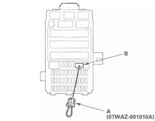
MPCS (MCIC) service connector 07WAZ-001010A
Test Mode 1
Check the PCM for DTCs, and troubleshoot PCM or F-CAN loss of communication errors first, then perform this diagnosis if the HDS is not available.
1. Check the No. 23 (10 A) fuse in the under-hood fuse/relay box and No. 10 (7.5 A) fuse in the under-dash fuse/relay box.
Are the fuses OK? YES-Go to step 2.
NO-Find and repair the cause of the blown fuse.
2. Remove the left kick panel.
3. Turn the ignition switch ON (II), and move the ceiling light switch to the middle (door) position.
4. Connect the MPCS service connector (A) to the MCIC socket (B) in the under-dash fuse/relay box.
5. Wait 5 seconds, and watch the ceiling light. When the ceiling light flashes quickly once, and then goes off the system is in Test Mode 1.
6. Check for B-CAN DTCs indicated by the gauge control module odometer/trip meter display while still in Test Mode 1. Push the odometer select/reset button to display the next code. After you get to the last code, the display shows END. If no DTCs are stored, the display will read NO.
Are any DTCs indicated? YES-Go to step 7.
NO-Go to step 10.
7. Record all DTCs and sort them.
8. Troubleshoot the DTCs in this order:
- Battery voltage DTCs
- Internal error DTCs
- Loss of communication DTCs (begin with the lowest number first; for example, if B1008 and B1011 are retrieved, troubleshoot B1008 first)
- Signal error DTCs
9. Clear the DTCs by pressing and holding the select/ reset button for about 13 seconds. You will hear a beep to confirm the code have been cleared.
Operate the devices that failed, and recheck for codes.
Test Mode 2
10. Remove the MPCS service connector from the under-dash fuse/relay box socket for 5-10 seconds, then re-insert it to enter Mode 2.
When the system enters Mode 2, the ceiling light will flash two times quickly and then go off.
NOTE: If the MPCS connector is disconnected for too short or too long of a time, or the ignition switch is turned OFF, the system will return to Test Mode 1.
11. The following table lists the circuits that can be checked in Test Mode 2. Operate the switch that is most closely related to the problem. If the circuit is OK, the ceiling light will blink once. If the circuit is faulty, there will be no indication.
MICU
- Audio switch
- Brake pedal position switch (ON)
- Dimmer switch (ON)
- Driver's door key cylinder switch (LOCK)*
- Driver's door key cylinder switch (UNLOCK)*
- Driver's door lock knob switch (LOCK)
- Driver's door lock knob switch (UNLOCK)
- Driver's door lock switch (LOCK)
- Driver's door lock switch (UNLOCK)
- Driver's door switch (OPEN)
- Front passenger's door lock knob switch (UNLOCK)*
- Front passenger's door lock switch (UNLOCK)
- Front passenger's door switch (OPEN)
- Hazard warning switch (ON)
- Headlight switch (OFF)
- Headlight switch (ON)
- Hood switch (OPEN)**
- Ignition key switch (ON)
- Left rear door lock knob switch (UNLOCK)*
- Left rear door switch (OPEN)
- Lighting switch (ON)
- Passing switch (ON)
- Rear window wiper switch (OFF)
- Rear window wiper switch (ON)
- Rear window washer switch (ON)
- Right rear door lock knob switch (UNLOCK)*
- Right rear door switch (OPEN)
- Tailgate latch switch (OPEN)
- Tailgate outside handle switch
- Transmission range switch (P)
- Turn signal switch (LEFT)
- Turn signal switch (RIGHT)
- Windshield washer switch (ON)
- Windshield wiper HI/LO switch
- Windshield wiper INT/LO switch
- Windshield wiper intermittent dwell time controller
- Windshield wiper MIST switch
*: A second key is necessary to check the key
cylinder inputs.
Be sure to rotate the key cylinder switch two
times to each position (lock and lock, unlock and
unlock) to ensure the door lock knob switch is in
the appropriate position.
* *: With security.
Does the ceiling light work properly in all switch positions? YES-Go to function and input test for the system related to the failure.
NO-Repair the open, short, or replace the faulty switch.
READ NEXT:
 Sleep and Wake-up Mode Test
1. Shift to the sleep mode:
Turn the ignition switch OFF, and remove the key. If the MICU receives no
signals from the inputs listed below, it
will go into sleep mode in less than 40 seconds.
Drive
DTC Troubleshooting
DTC B1000: Communication Bus Line Error
(Bus-off)
1. Clear the DTCs with the HDS.
2. Turn the ignition switch OFF, and then back ON (II).
3. Wait for 6 seconds or more.
4. Check for DTCs with the H
MICU Input Test
NOTE: Before testing, troubleshoot the B-CAN System Diagnosis Test Mode A.
1. Turn the ignition switch OFF.
2. Disconnect the under-dash fuse/relay box connectors E, F, G, K, R, and T.
NOTE: All con
SEE MORE:
Engine Block
Special Tools
Oil Seal Driver Attachment, 96 mm
Driver
Component Location Index
BAFFLE PLATE
LOVER BLOCK
DOWEL PINS
CRANKSHAFT OIL SEAL,
TRANSMISSION END
THRUST WASHERS
ENGINE BLOCK
CRANKSHAFT
MAIN BEARINGS
PISTON RINGS
PISTON PIN
PISTON
CONNECTING
DTC P0731: Problem in 1st Clutch and 1st
Clutch Hydraulic Circuit
NOTE: Before you troubleshoot, record all freeze data and any on-board
snapshot, and review General Troubleshooting Information.
1. Warm up the engine to normal operating
temperature (the radiator fan comes on).
2. Make sure that the transmission is filled to the
proper level, and check for fluid
