Honda CR-V: DTC Troubleshooting
DTC B1000: Communication Bus Line Error (Bus-off)
1. Clear the DTCs with the HDS.
2. Turn the ignition switch OFF, and then back ON (II).
3. Wait for 6 seconds or more.
4. Check for DTCs with the HDS.
Is DTCs B1000 and/or B1008 and B1011 indicated? YES-Go to step 5.
NO-Intermittent failure, the communication bus line is OK at this time. Check for poor connections or shorted wires.
5. Turn the ignition switch OFF.
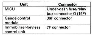
6. Disconnect the appropriate connector at each control unit in the table.
7. Turn the ignition switch ON (II).
8. Clear the DTCs with the HDS.
9. Turn the ignition switch OFF, and then back ON (II).
10. Wait for 6 seconds or more.
11. Check for DTCs with the HDS.
Is DTCs B1000 and/or B1008, B1011, and B1032 indicated? YES-Go to step 12.
NO-Faulty MICU; replace the under-dash fuse/ relay box.
12. Turn the ignition switch OFF.
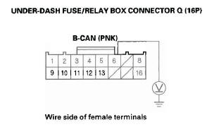
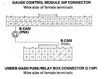
13. Check for continuity between the under-dash fuse/ relay box connector Ω (16P) No.6 terminal and body ground.
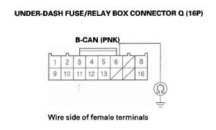
Is there continuity? YES-Repair a short to ground in the wire between the under-dash fuse/relay box and the affected control unit.
NO-Go to step 14.
14. Turn the ignition switch ON (II).
15. Measure voltage between the under-dash fuse/ relay box connector Ω (16P) No.6 terminal and body ground.
Is there voltage? YES-Repair the short to power in the wire between the under-dash fuse/relay box and the affected control unit.
NO-Go to step 16.
16. Turn the ignition switch OFF.
17. Reconnect the under-dash fuse/relay box connector Ω (16P).
18. Reconnect the gauge control module 36P connector.
19. Turn the ignition switch ON (II).
20. Clear the DTCs with the HDS.
21. Turn the ignition switch OFF, and then back ON (II).
22. Wait for 6 seconds or more.
23. Check for DTCs with the HDS.
Is DTC B1000 and/or B1008, B1011, and B1032 indicated? YES-Replace the gauge control module.
NO-Replace the immobilizer-keyless control unit.
DTC B1001: MICU Internal Error (CPU)
NOTE: If you are troubleshooting multiple DTCs, be sure to follow the instructions in B-CAN System Diagnosis Test Mode A.
1. Clear the DTCs with the HDS.
2. Turn the ignition switch OFF, and then back ON (II).
3. Wait for 6 seconds or more.
4. Check for DTCs with the HDS.
Is DTC B1001 indicated? YES-Faulty MICU; replace the under-dash fuse/ relay box.
NO-Intermittent failure, the MICU is OK at this time. Check for loose or poor connections. If the connections are good, check the battery condition (see page 22-65) and the charging system.
DTC B1002: MICU Internal Error (EEPROM)
NOTE: If you are troubleshooting multiple DTCs, be sure to follow the instructions in B-CAN System Diagnosis Test Mode A.
1. Clear the DTCs with the HDS.
2. Turn the ignition switch OFF, and then back ON (II).
3. Wait for 6 seconds or more.
4. Check for DTCs with the HDS.
Is DTC B1002 indicated? YES-Faulty MICU; replace the under-dash fuse/ relay box.
NO-Intermittent failure, the MICU is OK at this time. Check for loose or poor connections. If the connections are good, check the battery condition and the charging system.
DTC B1008: MICU Lost Communication with the Gauge Control Module (A/T Message)
DTC B1011: MICU Lost Communication with the Gauge Control Module (VSP/NE Message)
NOTE:
- If you are troubleshooting multiple DTCs, be sure to follow the instructions in B-CAN System Diagnosis Test Mode A.
- Before troubleshooting, check the No. 23 (10 A) fuse in the under-hood fuse/relay box and No. 10 (7.5 A) fuse in the under-dash fuse/relay box.
1. Clear the DTCs with the HDS.
2. Turn the ignition switch OFF, and then back ON (II).
3. Wait for 6 seconds or more.
4. Check for DTCs with the HDS.
Is DTCs B1008 and/or B1011 indicated? YES-Go to step 5.
NO-Intermittent failure, the gauge control module is OK at this time. Check for loose or poor connections between the gauge control module and the under-dash fuse/relay box connector Q (16P). If the connections are good, check the battery condition (see page 22-65) and the charging system.
5. Select the UNIT INFORMATION from the BODY ELECTRICAL system select menu, then enter the CONNECTED UNIT.
6. Check the condition of the gauge control module in the CONNECTED UNIT list.
Is NOT AVAILABLE indicated? YES-Go to step 7.
NO-Replace the gauge control module.
7. Measure voltage between-gauge control module 36P connector terminals No. 15 and No. 18, and between terminals No. 19 and No. 36.
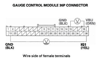
Is there battery voltage? YES-Go to step 8.
NO-Repair an open in the wire.
8. Turn the ignition switch OFF.
9. Disconnect the gauge control module 36P connector.
10. Disconnect the under-dash fuse/relay box connector Ω (16P).
11. Check for continuity between the under-dash fuse/ relay box connector Ω (16P) No.6 terminal and gauge control module 36P connector No. 20 terminal.
Is there continuity? YES-Replace the gauge control module.
NO-Repair an open in the wire between the MICU and the gauge control module.
DTC B1150 and B1900: Communication Bus Line Error (Bus-off)
1. Clear the DTCs with the HDS.
2. Turn the ignition switch OFF, and then back ON (II).
3. Wait for 6 seconds or more.
4. Check for DTCs with the HDS.
Are DTC B1000, B1008, B1011, and B1032 also indicated with DTCs B1150 and B1900? YES-Go to DTC B1000 troubleshooting.
NO-Intermittent failure, the system is OK at this time.
DTC B1032: MICU Lost Communication with the SRS Unit (CDS Message)
NOTE: If you are troubleshooting multiple DTCs, be sure to follow the instructions in B-CAN System Diagnosis Test Mode A.
1. Clear the DTCs with the HDS.
2. Turn the ignition switch OFF, and then back ON (II).
3. Wait for 6 seconds or more.
4. Check for DTCs with the HDS.
Is DTC B1032 indicated? YES-Go to step 5.
NO-Intermittent failure, the gauge control module is OK at this time. Check for loose or poor connections at the gauge control module 36P connector and the under-dash fuse/relay box connector Ω (16P). If the connections are good, check the battery condition and the charging system.
5. Check for DTCs with the HDS.
Are DTCs B1008 and B1011 also indicated with DTC B1032? YES-Check for an open in the communication circuit between the MICU and the gauge control module. If the circuit is bad, repair the open.
NO-Do the gauge control module input test.
DTC B1036: IG1 Line Input Error
NOTE: If you are troubleshooting multiple DTCs, be sure to follow the instructions in B-CAN System Diagnosis Test Mode A.
1. Clear the DTCs with the HDS.
2. Turn the ignition switch OFF, and then back ON (II).
3. Wait for 6 seconds or more.
4. Check for DTCs with the HDS.
Is DTC B1036 indicated? YES-Go to step 5.
NO-Intermittent failure, the system is OK at this time. Check for loose or poor connection at the gauge control module 36P connector and the under-dash fuse/relay box connector Ω (16P). If the connections are good, check the battery condition and the charging system.
5. Check for DTCs with the HDS.
Is DTC B1008 indicated with DTC B1036? YES-Go to DTC B1008 troubleshooting.
NO-Go to step 6.
6. Turn the ignition switch OFF.
7. Turn the ignition switch ON (II).
8. Measure voltage. between the gauge control module 36P connector No. 36 terminal and body ground.
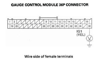
Is there battery voltage? YES-Faulty MICU or an open in the under-dash fuse/relay box internal circuit. Substitute a known-good under-dash fuse/relay box and recheck.
NO-Check No. 10 (7.5 A) fuse in the under-dash fuse/relay box. If the fuse is OK, check for an open in the wire between the under-dash fuse/relay box and the gauge control module, or repair a short in the wire between the under-dash fuse/relay box and the gauge control module.
READ NEXT:
 MICU Input Test
NOTE: Before testing, troubleshoot the B-CAN System Diagnosis Test Mode A.
1. Turn the ignition switch OFF.
2. Disconnect the under-dash fuse/relay box connectors E, F, G, K, R, and T.
NOTE: All con
Keyless/Power Door Locks/Security
System
Component Location Index
NAVIGATION UNIT or
AUDIO UNIT
IMMOBILIZER-KEYLESS
CONTROL UNIT
(Built-in receiver)
MICU (Built into the under-dash fuse/relay box)
HEADLIGHTS
HORN
HOOD SWITCH
SECUR
System Description
Security Alarm System
NOTE: This applies to EX and EX-L models.
The security alarm system is armed automatically after the doors, hood, and
tailgate are closed and locked. For the
system to arm, the
SEE MORE:
EVAP Canister Replacement
1. Lift the vehicle, and support it with jackstands.
2. Remove the cover (A).
3. Remove the EVAP canister baffle cover (A).
4. Disconnect the hoses (A) and the fuel subharness
6P connector (B).
5. Remove the bolts (C) and the EVAP canister bracket
(D).
6. Remove the EVAP canister (A) from the E
How the Passenger Airbag Off Indicator Works
This indicator alerts you that the
passenger’s front airbag has been
shut off because weight sensors
detect about 65 lbs (29 kg) or less
(the weight of an infant or small
child) on the front passenger’s seat.
It does not mean there is a problem
with the airbag.
Be aware that ob
