Honda CR-V: MICU Input Test
NOTE: Before testing, troubleshoot the B-CAN System Diagnosis Test Mode A.
1. Turn the ignition switch OFF.
2. Disconnect the under-dash fuse/relay box connectors E, F, G, K, R, and T.
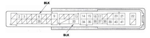
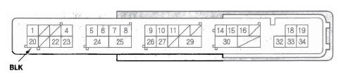
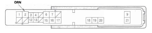
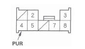
NOTE: All connector views are wire side of female terminals.
UNDER-DASH FUSE/RELAY BOX CONNECTOR E (42P)
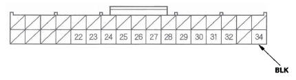
UNDER-DASH FUSE/RELAY BOX CONNECTOR F (34P)
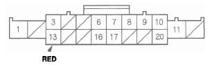
UNDER-DASH FUSE/RELAY BOX CONNECTOR G (21P)
UNDER-DASH FUSE/RELAY BOX CONNECTOR K (8P)
UNDER-DASH FUSE/RELAY BOX CONNECTOR R (20P)
UNDER-DASH FUSE/RELAY BOX CONNECTOR T (34P)
3. Inspect the connector and socket terminals to be sure they are all making good contact.
- If the terminals are bent, loose or corroded, repair them as necessary and recheck the system.
- If the terminals look OK, go to step 4.
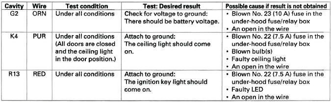
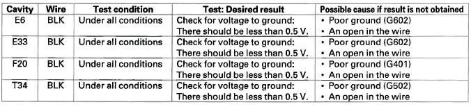
4. With the connector still disconnected, make these input tests at the appropriate connector.
- If any test indicates a problem, find and correct the cause, then recheck the system.
- If all the input tests prove OK, go to step 5.
5. Reconnect the connectors to the under-dash fuse/relay box, and make these input tests at the connectors.
- If any test indicates a problem, find and correct the cause, then recheck the system.
- If all the input tests prove OK, the MICU must be faulty; replace the under-dash fuse/relay box.
READ NEXT:
 Keyless/Power Door Locks/Security
System
Keyless/Power Door Locks/Security
System
Component Location Index
NAVIGATION UNIT or
AUDIO UNIT
IMMOBILIZER-KEYLESS
CONTROL UNIT
(Built-in receiver)
MICU (Built into the under-dash fuse/relay box)
HEADLIGHTS
HORN
HOOD SWITCH
SECUR
System Description
Security Alarm System
NOTE: This applies to EX and EX-L models.
The security alarm system is armed automatically after the doors, hood, and
tailgate are closed and locked. For the
system to arm, the
DTC Troubleshooting
DTC B1026: Front Passenger's Door Lock
Switch Signal Error (LOCK/UNLOCK)
NOTE: If you are troubleshooting multiple DTCs, be
sure to follow the instructions in B-CAN System Diagnosis Test Mode A.
1. Cl
SEE MORE:
Rear Seat
Rear Seat Armrest Removal/Installation
NOTE: Take care not to tear the seams or damage the
seat covers.
1. Remove the E-ring (A) from the right side portion
on the armrest pivot.
2. Slide the armrest (A) toward the right side, then
release the left pivot shaft (B) from the bushing (C).
3. Release
Dust and Pollen Filter
This filter removes the dust and
pollen that is brought in fromthe
outside through the heating and
cooling system/climate control
system.
Have your dealer replace this filter
when this service is indicated by a
maintenance message on the
information display. It should be
replaced ev
