Honda CR-V: General Troubleshooting Information
How to Check for DTCs with the Honda Diagnostic System (HDS)
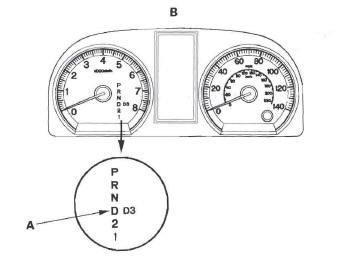
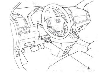
When the powertrain control module (PCM) senses an abnormality in the input or output system, the D indicator (A) in the gauge control module (tach) (B) will usually blink.
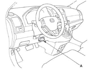
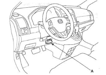
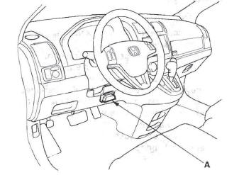
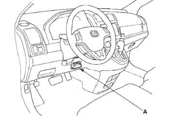
When the Honda Diagnostic System (HDS) is connected to the data link connector (DLC) (A) (located behind the driver's dashboard lower cover) and the SCS mode is selected, it will indicate the diagnostic trouble code (DTC) when the ignition switch is turned ON (II) and the appropriate menu is selected.
If the D indicator or malfunction indicator lamp (MIL) has been reported on, or if a driveability problem is suspected, do this:
1. Connect the HDS to the DLC. (See the HDS user's manual for specific instructions.)
2. Turn the ignition switch ON (II), select A/T system, and observe the DTC in the DTCs MENU on the HDS screen.
NOTE: If the HDS does not communicate with the PCM, troubleshoot the DLC circuit.
3. Record all fuel and emissions DTCs, and A/T DTCs, and freeze data.
4. If there is a fuel and emissions DTC, first check the fuel and emissions system as indicated by the DTC (except for DTC P0700, which means there is one or more A/T DTCs, and no problems were detected in the fuel and emissions circuit of the PCM).
5. Clear the DTC and data.
6. Drive the vehicle for several minutes under the same conditions as those indicated by the freeze data, and then recheck for a DTC. If the A/T DTC returns, go to the indicated DTC's troubleshooting.
If the DTC does not return, there was an intermittent problem within the circuit. Make sure all pins and terminals in the circuit are tight.
Symptom Troubleshooting Versus DTC Troubleshooting
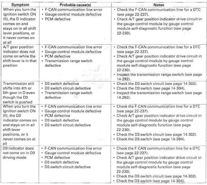
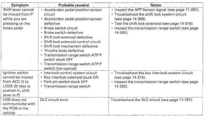
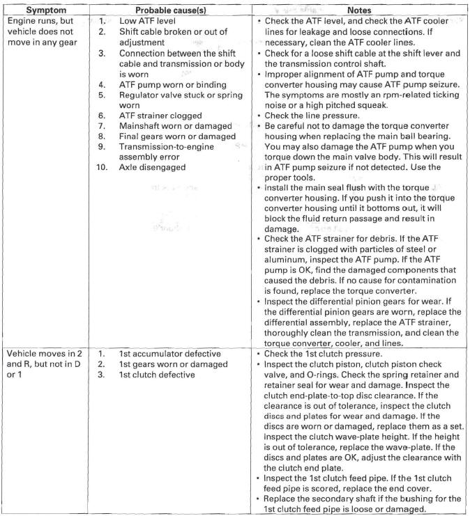
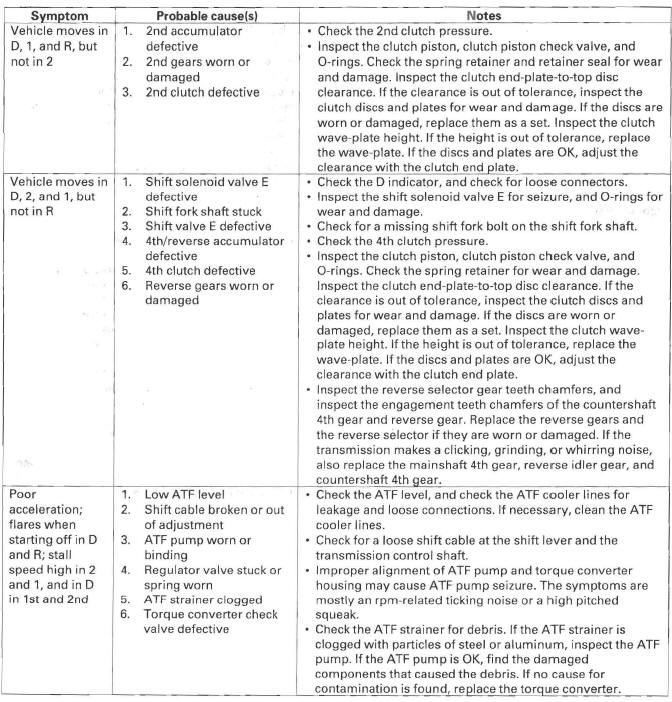
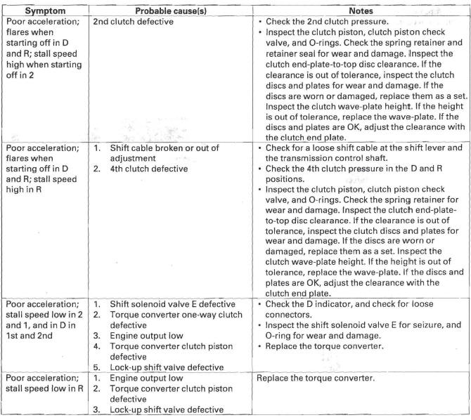
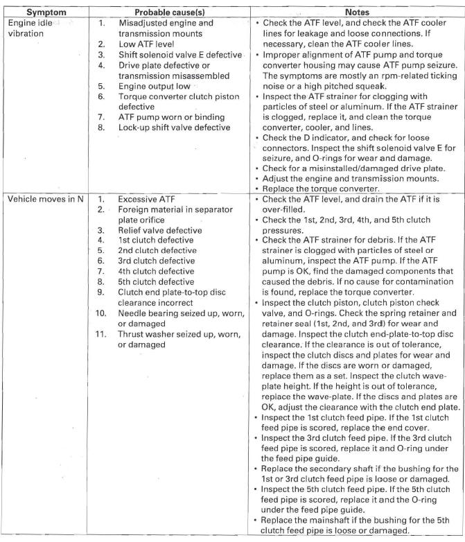
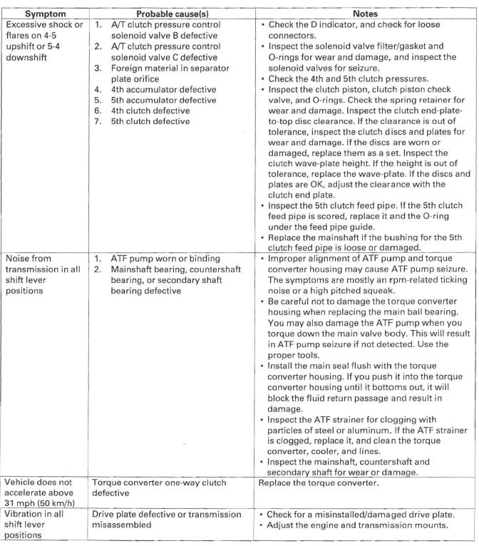
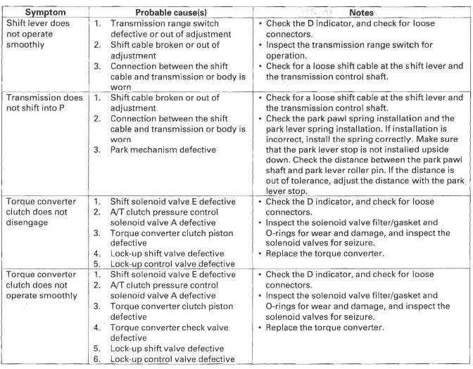
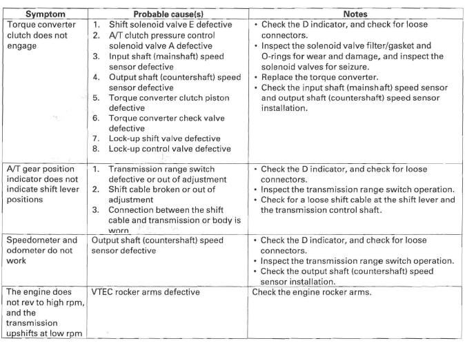
Some symptoms will not trigger diagnostic trouble codes (DTCs) or cause the D indicator to blink. If the malfunction indicator lamp (MIL) was reported ON or the D indicator has been blinking, check for DTCs. If the vehicle has an abnormal symptom, and there are no DTCs stored, do the symptom troubleshooting. Check the list of probable cause(s) for the symptom, in the sequence listed, until you find the problem.
How to Check for DTCs with the SCS Mode (retrieving the flash codes)
NOTE: The preferred method is to use the HDS to retrieve the P-code.
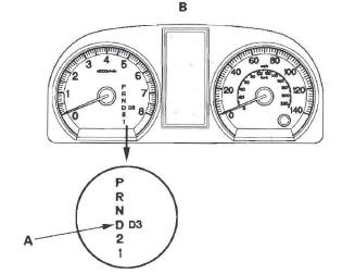
When the PCM senses an abnormality in the input or output system, the D indicator (A) in the gauge control module (tach) (B) will usually blink.
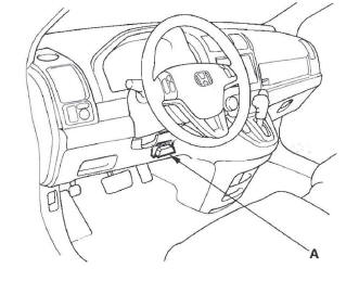
When the D indicator has been reported on, connect the HDS to the DLC (A) (located behind the driver's dashboard lower cover). Turn the ignition switch ON (II), select SCS mode, then the D indicator will indicate flash the DTC.
If the D indicator and the MIL come on at the same time, or if a driveability problem is suspected, do this:
1. Connect the HDS to the DLC. (See the HDS user's manual for specific instructions.)
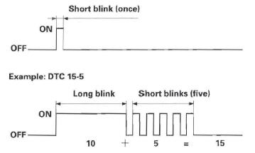
2. Turn the ignition switch ON (II), select SCS mode, then observe the D indicator in the gauge control module. Codes 1 through 9 are indicated by individual short blinks. Code 10 and above are indicated by a series of long and short blinks. One long blink equals 10 short blinks. Add the long and short blinks together to determine the code.
NOTE: If the HDS does not communicate with the PCM, troubleshoot the DLC circuit.
Example: DTC 1-1
3. Record all fuel and emissions DTCs and A/T DTCs.
4. If there is a fuel and emissions DTC, first check the fuel and emissions system as indicated by the DTC (except DTC 70, which means there is one or more A/T DTCs, and no problems were detected in the fuel and emissions circuit of the PCM).
5. Clear the DTC and data.
6. Drive the vehicle for several minutes under the same conditions as those indicated by the freeze data, and then recheck for DTCs. If the A/T DTC returns, go to the indicated DTC's troubleshooting.
If the DTC does not return, there was an intermittent problem within the circuit. Make sure all pins and terminals in the circuit are tight.
How to Troubleshoot Circuits at the PCM Connectors
NOTE: The PCM overwrites data and monitors the EVAP system for up to 15 minutes after the ignition switch is turned OFF. Jumping the SCS line after turning the ignition switch OFF cancels this function. Disconnecting the PCM during this function, without jumping the SCS line first, can damage the PCM.
1. Connect the HDS to the DLC (A).
2. Jump the SCS line with the HDS.
NOTE: If the HDS does not communicate with the PCM, troubleshoot the DLC circuit.
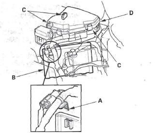
3. Remove the harness clamp bracket (A) from the PCM cover.
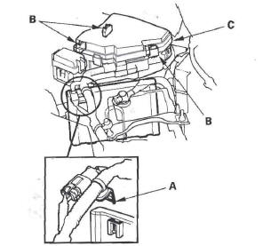
4. Release the three clips (S) securing the under-hood fuse/relay box (C), and lift up the box.
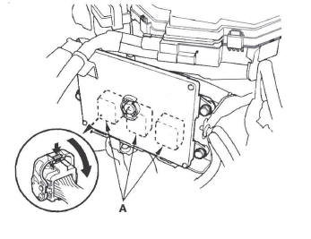
5. Disconnect PCM connectors (A), and probe the terminals in the inspection port on the terminal side of the connectors.
6. Check the connector inspection port (A) size, and select a suitable pin probe.
7. Connect one side of the patch cord (A) terminal to a digital multi meter (B), and connect the other side of the patch cord terminals to a commercially available banana jack (Pomona Electronics Tool No. 3563 or equivalent) (C).
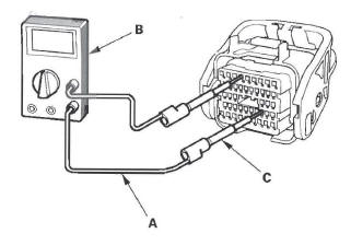
8. Gently slide the pin probe into the inspection port at the connector terminal side. Always use the inspection port. Do not slide the probe into the connector terminals.
NOTICE
- For accurate result, always use the pin probe (male).
- To prevent damage to the connector terminals, do not insert test equipment probes, paper clips, or other substitutes as they can damage the terminals. Damaged terminals cause a poor connection and an incorrect measurement.
- Do not puncture the insulation on a wire.
Punctures can cause poor or intermittent electrical connections.
Clear A/T DTCs Procedure
1. Connect the HDS to the DLC (A).
2. Turn the ignition switch ON (II).
3. Clear the DTC(s) on the HDS screen.
OBD Status
The OBD status shows the current system status of each DTC and all of the parameters. This function is used to see if the technician's repair was successfully finished. The results of diagnostic tests for the DTC are displayed as:
- PASSED: On-board diagnosis is successfully finished.
- FAILED: On-board diagnosis has finished but failed.
- NOT COMPLETED: The on-board diagnosis was running but is out of the enable conditions of the DTC.
How to End a Troubleshooting Session
This procedure must be done after any troubleshooting.
1. Reset the PCM with the HDS while the engine is stopped.
2. Turn the ignition switch OFF.
3. Turn the ignition switch ON (II), and wait for 30 seconds.
4. Turn the ignition switch OFF, and disconnect the HDS from the DLC.
5. Do the PCM idle learn procedure.
6. Start the engine with the shift lever in the P or N position, and warm it up to normal operating temperature (the radiator fan comes on).
7. To verify that the problem is repaired, test-drive the vehicle for several minutes at speeds over 30 mph (50 km/h) or under the same conditions as those indicated by the freeze data.
PCM Updating and Substitution for Testing
Special Tools Required
- Honda diagnosis system (HDS) TDSGD2200
- Honda interface module (HIM) EQS05A35570
- HDS pocket tester TDSS3557011401
These special tools are available through the American Honda Tool and Equipment Program 1-888-424-6857.
Use this procedure when you have to substitute a known-good PCM in a troubleshooting procedure.
Update the PCM only if the PCM does not already have the latest software loaded.
NOTE: Do not turn the ignition switch OFF while updating the PCM. If you turn the ignition switch OFF before completion, the PCM can be damaged.
How to Update the PCM
NOTE:
- Make sure you have the latest software on the HCS.
- To ensure the latest program is installed, do a PCM update whenever the PCM is substituted or replaced.
- You cannot update a PCM with the program it already has. It will only accept a new program.
- Before you update the PCM, make sure the battery is fully charged.
- To prevent PCM damage, do not operate anything electrical (audio system, brakes, A/C, power windows, moonroof (if equipped), or door locks) during the update.
- If you need to diagnose the Honda interface module (HIM) because the HIM's red (# 3) light came on or was flashing during the update, leave the ignition switch in the ON (II) position when you disconnect the HIM from the data link connector (DLC). This will prevent PCM damage.
- High temperature in the engine compartment might cause the PCM to become too hot to run the update. If the engine has been running before this procedure, open the hood and cool the engine compartment.
1. Turn the ignition switch ON (II), but do not start the engine.
2. Connect the HDS to the DLC (A).
3. Make sure the HDS communicates with the PCM. If it does not, go to the DLC circuit troubleshooting. If you did the DLC circuit troubleshooting, skip steps 4 and 5, then clean the throttle body after step 9.
4. Select the INSPECTION MENU with the HDS.
5. Select the TP POSITION CHECK in the ETCS TEST with the HDS.
NOTE: If there is no result from TP POSITION CHECK, clean the throttle body after this procedure.
6. If the HDS does not have the update function, disconnect the HDS from the DLC, and connect the Honda interface module (HIM) to the DLC.
7. If the software in the PCM is the latest, disconnect the HDS or the HIM from the DLC, and go back to the procedure that you were doing. If the software in the PCM is not the latest, do the PCM update procedure as described on the HIM label or in the PCM update system.
NOTE: If the PCM update system requires you to cool the PCM, follow what is shown on the screen.
8. Do the PCM idle learn procedure/
9. Do the crank pattern clear/crank pattern learn (pulser F/B) procedure/
How to Substitute the PCM
1. Make sure you have the anti-theft code for the audio or the navigation system (if equipped).
2. Connect the HDS to the DLC (A).
3. Turn tl1e ignition switch ON (II).
4. Make sure the HDS communicates with the PCM. If it does not, go to the DLC circuit troubleshooting. If you did the DLC circuit troubleshooting, skip steps 5 thru 9, then clean the throttle body after substituting the PCM.
5. Select the INSPECTION MENU with the HDS.
6. Select the TP POSITION CHECK in the ETCS TEST with the HDS.
NOTE: If the result of TP POSITION CHECK was failed, clean the throttle body after this procedure.
7. Turn the ignition switch OFF.
8. Remove the battery.
9. Remove the harness clamp bracket (A) from the PCM cover (B).
10. Release the three clips (C) securing the under-hood fuse/relay box (D), and lift up the box.
11. Remove the bolts (A), and remove the PCM (B).
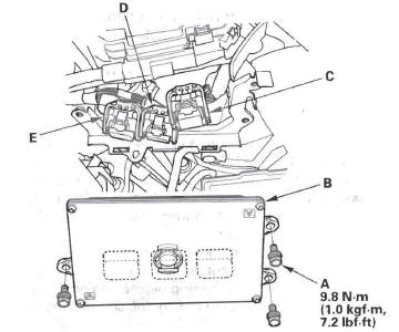
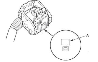
12. Disconnect the PCM connectors A (C), B (D), and C (E).
NOTE: PCM connectors A, B, and C have symbols
(A= , B=
, B= ,
C=
,
C= ) embossed on them for
identification.
) embossed on them for
identification.
13. Install the PCM and the battery in the reverse order of removal.
14. Turn the ignition switch ON (II).
NOTE: DTC P0630 "VIN not Programmed or Mismatch" will be stored because VIN has not been programmed into the PCM. Ignore it, and continue this procedure.
15. Input the VIN to the PCM with the HDS.
16. Update the PCM if it does not have the latest software.
17. Select the IMMOBILIZER SYSTEM with the HDS.
18. Rewrite the immobilizer code with the PCM replacement procedure in the HDS; it allows you to start the engine.
19. Reset the PCM with the HDS.
20. Do the PCM idle learn procedure.
21. Do the crank pattern learn procedure.
22. Enter the anti-theft code for the audio or the navigation system (if equipped), then enter the audio presets, and set the clock.
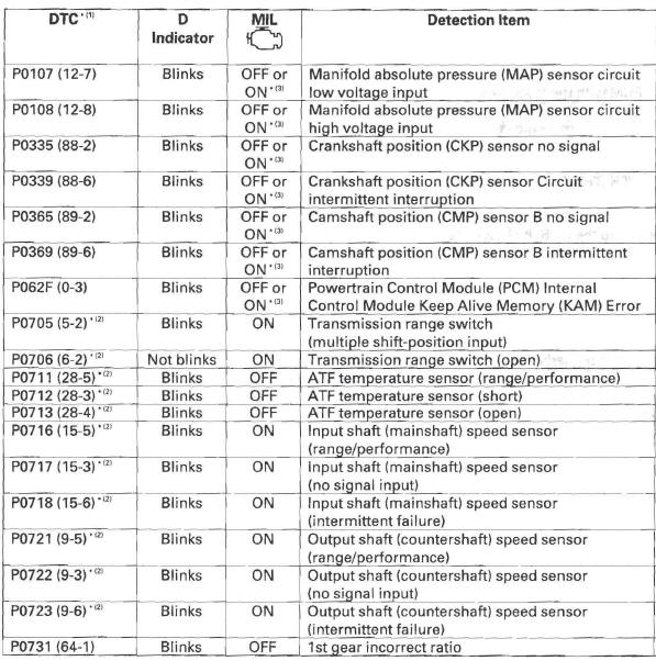
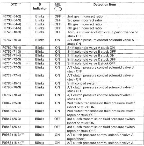
DTC Troubleshooting Index
NOTE: Before you troubleshoot. record all freeze data and any on-board snapshot, and review General Troubleshooting Information.
NOTE:
* (1): The DTC in parentheses is the Honda code that you will see when you
use the SCS mode. The first number(s)
before the - (hyphen) is the flash code the D indicator indicates when the data
link connector (DLC) is connected
to the HDS, and in the SCS mode.
* (2): This code is caused by an electrical circuit problem and cannot be caused
by a mechanical problem in the
transmission.
* (3): The MIL comes on when the PGM-FI control system detects the same failure.
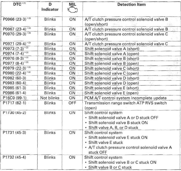
NOTE: Before you troubleshoot, record all freeze data and any on-board snapshot, and review General Troubleshooting Information.
NOTE:
* (1): The DTC in parentheses is the Honda code that you will see when you
use the SCS mode. The first number(s)
before the - (hyphen) is the flash code the D indicator indicates when the data
link connector (DLC) is connected
to the HDS, and in the SCS mode.
* (2): This code is caused by an electrical circuit problem and cannot be caused
by a mechanical problem in the
transmission.
NOTE: Before you troubleshoot. record all freeze data and any on-board snapshot, and review General Troubleshooting Information.
NOTE:
* (1): The DTC in parentheses is the Honda code that you will see when you
use the SCS mode. The first number(s)
before the - (hyphen) is the flash code the D indicator indicates when the data
link connector (DLC) is connected
to the HDS, and in the SCS mode.
* (2): This code is caused by an electrical circuit problem and cannot be caused
by a mechanical problem in the
transmission.
NOTE: Before you troubleshoot, record all freeze data and any on-board snapshot, and review General Troubleshooting Information.
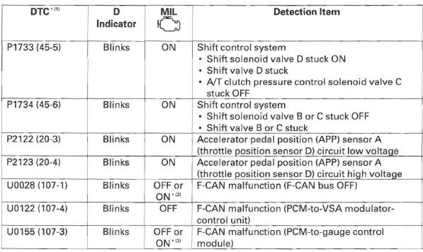
NOTE:
* (1): The DTC in parentheses is the Honda code that you will see when you
use the SCS mode. The first number(s)
before the - (hyphen) is the flash code the D indicator indicates when the data
link connector (DLC) is connected
to the HDS, and in the SCS mode.
* (2): The MIL comes on when the PGM-FI control system detects the same failure.
Symptom Troubleshooting Index
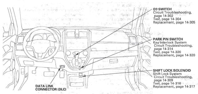
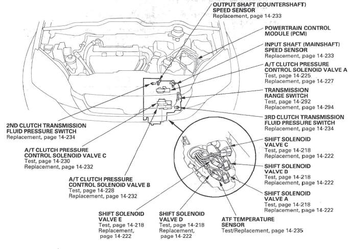
Component Location Index
READ NEXT:
 General Operation
The automatic transmission is a combination of a 3-element torque converter
and triple-shaft electronically controlled
unit which provides 5 speeds forward and 1 reverse. The entire unit is
position
Power Flow
P Position
Hydraulic pressure is not applied to the clutch. Power is not transmitted to
the countershaft. The countershaft is locked
by the park pawl, interlocking the park gear.
N Position
Engine po
SEE MORE:
VSA (Vehicle Stability Assist) System Components
Component Location Index
VSA MODULATOR-CONTROL UNIT
Removal and Installation
UNDER-HOOD FUSE/RELAY BOX
DATA LINK
CONNECTOR (DLC)
STEERING ANGLE SENSOR
Replacement
VSA OFF SWITCH
Test
RIGHT-REAR WHEEL SENSOR
Replacement
HUB BEARING UNIT
(MAGNETIC ENCODER)
Replace
Fuel Pump Circuit Troubleshooting
If you suspect a problem with the fuel pump, check that
the fuel pump actually runs; when it is on, you will hear
some noise if you listen to the fuel fill port with the fuel
f ill cap removed. The fuel pump should run for
2 seconds when the ignition switch is first turned on. If
the fuel pump does
