Honda CR-V: Power Flow
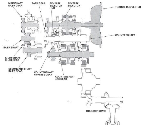
P Position
Hydraulic pressure is not applied to the clutch. Power is not transmitted to the countershaft. The countershaft is locked by the park pawl, interlocking the park gear.
N Position
Engine power transmitted from the torque converter drives the mainshaft idler gear, the idler shaft idler gear, and the secondary shaft idler gear, but hydraulic pressure is not applied to the clutches. Power is not transmitted to the.
counters haft. In this position, the position of the reverse selector differs according to whether the shift lever shifted from the D or R position:
- When shifted from the D position, the reverse selector engages with the countershaft 4th gear and the reverse selector hub, and the 4th gear engages with the countershaft.
- When shifted from the R position, the reverse selector engages with the countershaft reverse gear and the reverse selector hub, and the reverse gear engages with the countershaft.
NOTE: The illustration shows the 4WD transmission; 2WD does not have the transfer mechanism.
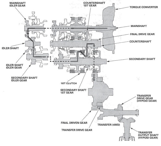
1st Gear
- Hydraulic pressure is applied to the 1st clutch, then the 1st clutch engages the secondary shaft 1st gear with the secondary shaft.
- The mainshaft idler gear drives the secondary shaft via the idler shaft idler gear and the secondary shaft idler gear.
- The secondary shaft 1st gear drives the countershaft 1st gear and the countershaft.
- Power is transmitted to the final drive gear, which in turn drives the final driven gear, and the transfer drive gear (4WD).
- 4WD: The transfer drive gear drives the transfer drive gear (hypoid gear) and the transfer output shaft (hypoid gear).
NOTE: The illustration shows the 4WD transmission; 2WD does not have the transfer mechanism.
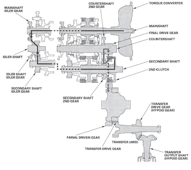
2nd Gear
- Hydraulic pressure is applied to the 2nd clutch, then the 2nd clutch engages the secondary shaft 2nd gear with the secondary shaft.
- The mainshaft idler gear drives the secondary shaft via the idler shaft idler gear and the secondary shaft idler gear.
- The secondary shaft 2nd gear drives the countershaft 2nd gear and the countershaft.
- Power. is transmitted to the final drive gear, which in turn drives the final driven gear, and the transfer drive gear (4WD).
- 4WD: The transfer drive gear drives the transfer drive gear (hypoid gear) and the transfer output shaft (hypoid gear).
NOTE: The illustration shows the 4WD transmission; 2WD does not have the transfer mechanism.
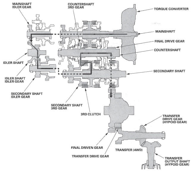
3rd Gear
- Hydraulic pressure is applied to the 3rd clutch, then the 3rd clutch engages the secondary shaft 3rd gear with the secondary shaft.
- The mainshaft idler gear drives the secondary shaft via the idler shaft idler gear and secondary shaft idler gear.
- The secondary shaft 3rd gear drives the countershaft 3rd gear and the countershaft.
- Power is transmitted to the final drive gear, which in turn drives the final driven gear, and the transfer drive gear ' (4WD).
- 4WD: The transfer drive gear drives the transfer drive gear (hypoid gear) and the transfer output shaft (hypoid gear).
NOTE: The illustration shows the 4WD transmission; 2WD does not have the transfer mechanism.
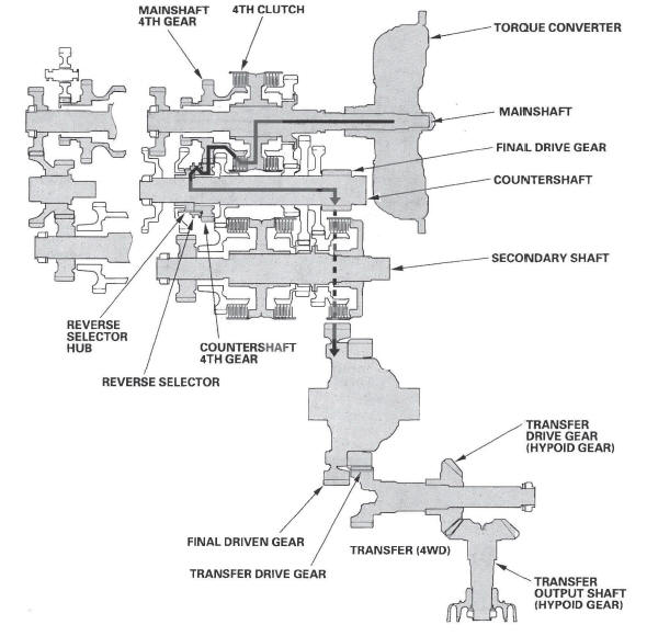
4th Gear
- Hydraulic pressure is applied to the servo valve to engage the reverse selector with the countershaft 4th gear and reverse selector hub while the shift lever is in forward range (D, 2, and 1 positions).
- Hydraulic pressure is also applied to the 4th clutch, then the 4th clutch engages the mainshaft 4th gear with the mainshaft.
- The mainshaft 4th gear drives the countershaft 4th gear and the countershaft.
- Power is transmitted to the final drive gear, which in turn drives the final driven gear, and the transfer drive gear (4WD).
- 4WD: The transfer drive gear drives the transfer drive gear (hypoid gear) and the transfer output shaft (hypoid gear).
NOTE: The illustration shows the 4WD transmission; 2WD does not have the transfer mechanism.
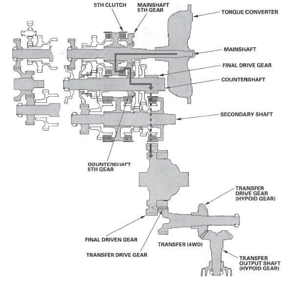
5th Gear
- Hydraulic pressure is applied to the 5th clutch, then the 5th clutch engages the mainshaft 5th gear with the mainshaft.
- The mainshaft 5th gear drives the countershaft 5th gear and the countershaft.
- Power is transmitted to the final drive gear, which in turn drives the final driven gear, and the transfer drive gear (4WD).
- 4WD: The transfer drive gear drives the transfer drive gear (hypoid gear) and the transfer output shaft (hypoid gear).
NOTE: The illustration shows the 4WD transmission; 2WD does not have the transfer mechanism.
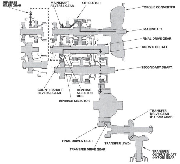
R Position
- Hydraulic pressure is applied to the servo valve to engage the reverse selector with the countershaft reverse gear and reverse selector hub while the shift lever is in the R position.
- Hydraulic pressure is also applied to the 4th clutch, then the 4th clutch engages the mainshaft reverse gear with the mainshaft.
- The mainshaft reverse gear drives the countershaft reverse gear via the reverse idler gear.
- The rotation direction of the countershaft reverse gear is changed by the reverse idler gear.
- The countershaft reverse gear drives the countershaft via the reverse selector, which drives the reverse selector hub.
- Power is transmitted to the final drive gear, which in turn drives the final driven gear, and the transfer drive gear (4WD).
- 4WD: The transfer drive gear drives the transfer drive gear (hypoid gear) and the transfer output shaft (hypoid gear).
NOTE: The illustration shows the 4WD transmission; 2WD does not have the transfer mechanism.
READ NEXT:
 Electronic Control System
Functional Diagram
The electronic control system consists of the powertrain control module (PCM),
sensors, and solenoid valves.
Shifting and lock-up are electronically controlled for comfortable dri
Hydraulic Controls
Valve Bodies
The valve body includes the main valve body, the regulator valve body, and
the servo body. The ATF pump is driven
by splines on the left end of the torque converter which is attached to
Hydraulic Flow
Distribution of Hydraulic Pressure
As the engine turns, the ATF pump starts to operate. Automatic transmission
fluid (ATF) is drawn through the ATF
strainer (filter) and discharged into the hydraulic
SEE MORE:
Adding Engine Oil
Unscrew and remove the engine oil
fill cap on top of the valve cover.
Pour in the oil slowly and carefully
you do not spill any. Clean up any
spills immediately. Spilled oil could
damage components in the engine
compartment.
Reinstall the engine oil fill cap, and
tighten it securely.
F-CAN Circuit Troubleshooting
NOTE: Information marked with an asterisk (*) applies
to the CANL line.
1. Turn the ignition switch OFF.
2. Jump the SCS line with the HDS.
3. Disconnect PCM connector A (44P), then disconnect
the HDS.
4. Measure resistance between PCM connector
terminals A36 and A37.
Is there about 95- 116 Ω
