Honda CR-V: Electronic Control System
Functional Diagram
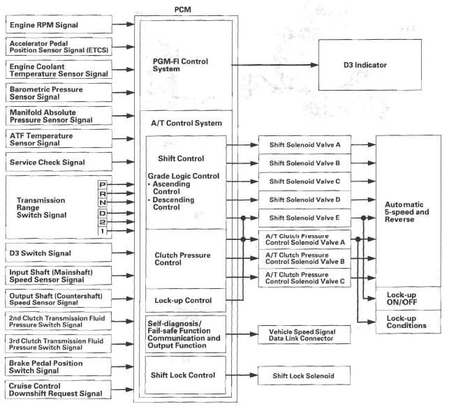
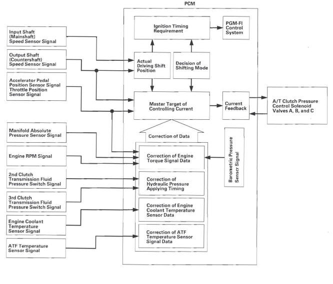
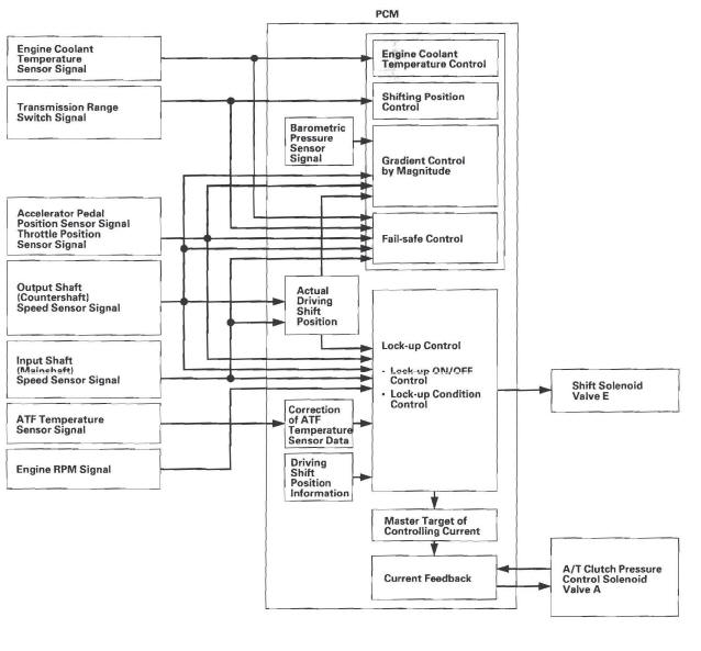
The electronic control system consists of the powertrain control module (PCM), sensors, and solenoid valves.
Shifting and lock-up are electronically controlled for comfortable driving under all conditions.
The PCM receives input signals from the sensors, switches, and other control units, processes data, and outputs signals for the engine control system and A/T control system. The A/T control system includes shift control, grade logic control, clutch pressure control, and lock-up control.
The PCM actuates the shift solenoid valves and the A/T clutch pressure control solenoid valves to control shifting transmission gears and torque converter.
Shift Control
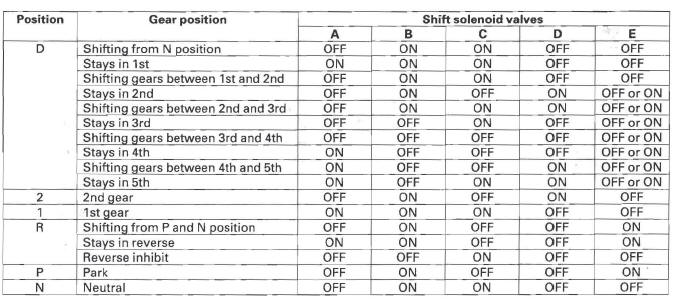
The PCM instantly determines which gear should be selected by various signals sent from sensors and switches, and it actuates the shift solenoid valves A, B, C, D, and E to control shifting transmission gears.
Shift solenoid valves are a normally closed type. Shift solenoid valve opens the port of shift solenoid valve pressure leading to shift valves while shift solenoid valve is turned ON by the PCM, and closes the port when shift solenoid valve is OFF.
The combination of driving signals to shift solenoid valves A, B, C, D, and E are shown in the table.
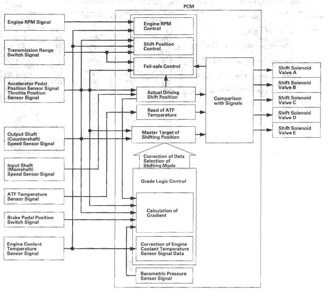
Shift Control - Grade logic Control
The grade logic control system has been adopted to control shifting in the D position. The PCM compares actual driving conditions with programmed driving conditions, based on signals from the accelerator pedal position sensor, the throttle position sensor, the engine coolant temperature sensor, the barometric pressure sensor, the brake pedal position switch signal, and the shift lever position signal, to control shifting while the vehicle is ascending or descending a slope.
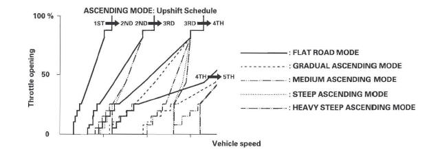
Grade Logic Control: Ascending Control
When the PCM determines that the vehicle is climbing a hill in the D position, the grade logic system extends the engagement area of 2nd, 3rd, and 4th gears to prevent the t transmission from frequently shifting between 2nd and 3rd gears, between 3rd and 4th gears, and between 4th and 5th gears, so the vehicle can run smooth and have more power when needed.
Shift programs stored in the PCM between 2nd and 3rd gears, between 3rd and 4th gears, and between 4th and 5th gears, enable it to automatically select the most suitable gear according to the magnitude of a gradient.
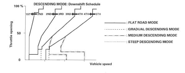
Grade Logic Control: Descending Control
When the PCM determines that the vehicle is going down a hill in the D position, the shift-up speed from 4th to 5th gear, from 3rd to 4th gear, and from 2nd to 3rd gear (when the throttle is closed) becomes faster than the set speed for flat road driving to widen the 4th gear, 3rd gear, and 2nd gear driving area. This, in combination with engine braking from the deceleration lock-up, achieves smooth driving when the vehicle is descending. There are three descending modes with different 4th gear driving areas, 3rd gear driving areas, and 2nd gear driving areas according to the magnitude of a gradient stored in the PCM. When the vehicle is in 5th gear or 4th gear, and you are decelerating when you are applying the brakes on a steep hill the transmission will downshift to lower gear. When you accelerate, the transmission will then return to a higher gear.
Shift Control - D Position D3 Driving Mode Control
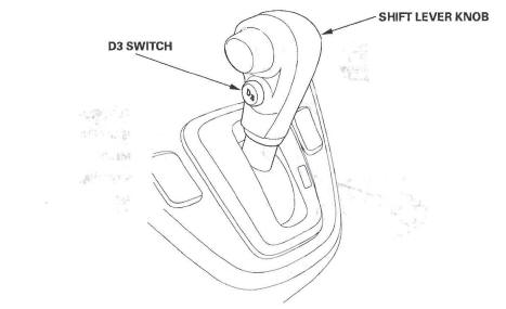
The automatic transmission is provided with the D3 driving mode in the D position. The D position has two modes; general driving mode (shifts gears automatically 1st through 5th), and the D3 driving mode (shifts gears automatically 1st through 3rd). The transmission mode switches by pushing the D3 switch on the shift lever knob in the D position.
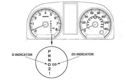
In the D3 driving mode, the D3 indicator next to the D indicator in the gauge assembly comes on. The D3 driving mode is cancelled by pushing the D3 switch, and the D3 indicator goes off. Also, the D3 driving mode is cancelled when the ignition switch is turned off. When the shift lever is moved out of the D position in the D3 driving mode, the D3 indicator goes off, but the transmission returns into D3 driving mode when returning the shift lever into the D position, and the D3 indicator comes on.
Clutch Pressure Control
The PCM actuates A/T clutch pressure control solenoid valves A, S, and C to control the clutch pressure. When shifting between gears, the clutch pressure regulated by A/T clutch pressure control solenoid valves A, S, and C engages and disengages the clutch smoothly.
The PCM receives input signals from the various sensors and switches, processes data, and outputs current to A/T clutch pressure control solenoid valves A, B, and C.
Lock-up Control
The shift solenoid valve E controls the hydraulic pressure to switch the lock-up shift valve and lock-up ON and OFF.
The PCM actuates the shift solenoid valve E and the A/T clutch pressure control solenoid valve A to start lock-up. The A/T clutch pressure control solenoid valve A applies and regulates hydraulic pressure to the lock-up control valve to control the volume of the lock-up.
The lock-up mechanism operates in the D position (2nd, 3rd, 4th, and 5th), and in the D position D3 driving mode (2nd and 3rd).
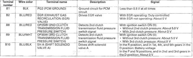
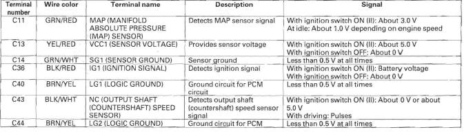
PCM A/T Control System Electrical Connections
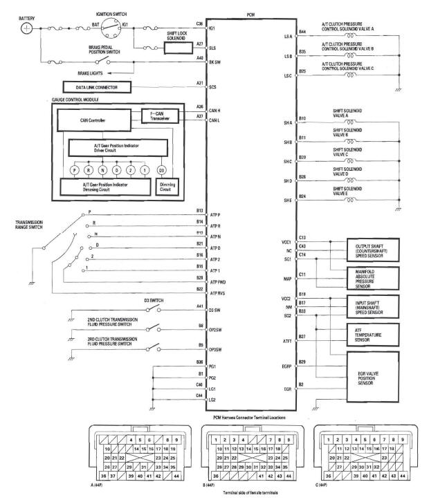
PCM A/T Control System Inputs and Outputs
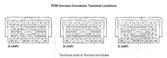
PCM CONNECTOR A (44P)
PCM CONNECTOR B (44)
PCM CONNECTOR B (44P)
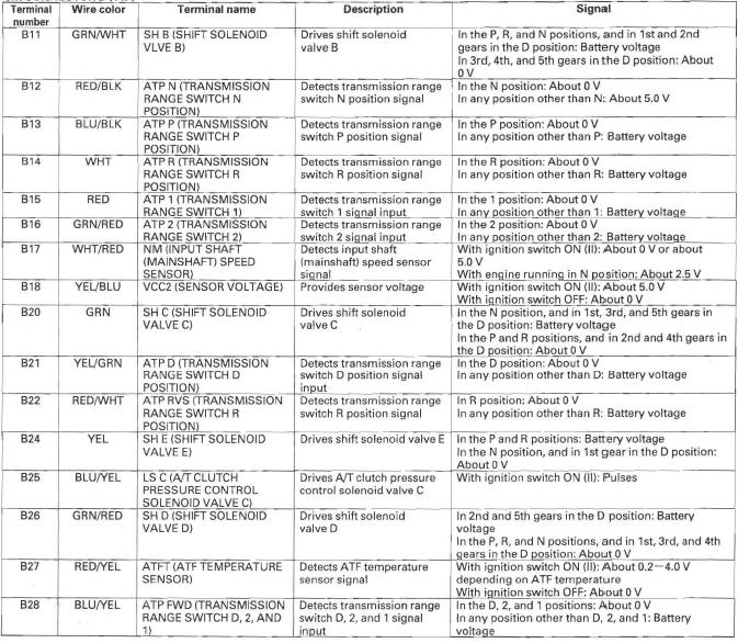
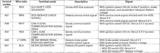
PCM A/T Control System Inputs and Outputs
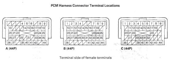
PCM CONNECTOR B (44P)
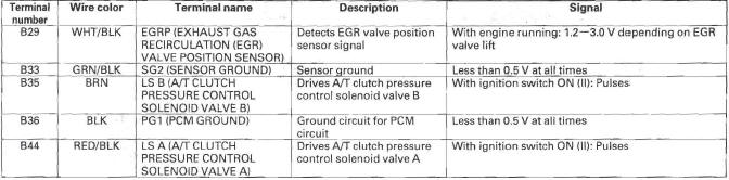
PCM CONNECTOR C (44P)
READ NEXT:
 Hydraulic Controls
Valve Bodies
The valve body includes the main valve body, the regulator valve body, and
the servo body. The ATF pump is driven
by splines on the left end of the torque converter which is attached to
Hydraulic Flow
Distribution of Hydraulic Pressure
As the engine turns, the ATF pump starts to operate. Automatic transmission
fluid (ATF) is drawn through the ATF
strainer (filter) and discharged into the hydraulic
Lock-up System
The lock-up mechanism of the torque converter clutch operates in D position
(2nd, 3rd, 4th, and 5th), and in D position
D3 driving mode (2nd and 3rd). The pressurized fluid is drained from the back o
SEE MORE:
Mode Control
Use the mode control buttons to
select the vents air flows from. Some
air will flow from the dashboard
corner vents in all modes.
Air flows from the center
and corner vents in the dashboard.
Airflow is divided between
the vents in the dashboard and the
floor vents.
Air flo
Removing a Disc
To remove a disc from the audio unit,
fold back the screen by pressing the
OPEN button. Press
the disc eject button (
) to
remove the disc. If you eject the disc,
but do not remove it from the slot,
the system will automatically reload
it after 10 seconds and put it in pause
mode.
