Honda CR-V: General Troubleshooting Information
DTC (Diagnostic Trouble Codes)
The self-diagnostic function of the SRS system allows it to locate the causes of system problems and then store this information in memory. For easier troubleshooting, this data can be retrieved via a data link circuit.
- When you turn the ignition switch ON (II), the SRS indicator comes on. If it goes off after 6 seconds, the system is normal, and is not currently detecting any abnormality.
- If there is an abnormality, the system locates and defines the problem, stores this information in memory, and turns the SRS indicator on: The data remains in the memory even when the ignition switch is turned off or if the battery is disconnected.
- The data is stored in memory as a diagnostic trouble code (DTC).
- DTCs are either latching or resetting depending on the malfunction. With resetting DTCs, the SRS indicator goes off the next time the ignition switch is turned ON and the system is normal, but the DTC is still stored. With latching DTCs, the SRS indicator does not turn OFF until the malfunction is repaired and the DTC is cleared.
- When you connect the HDS to the 16P data link connector (DLC), you can retrieve a more detailed DTC in the Honda Systems "SRS" menu.
- After reading and recording the DTC, proceed with the troubleshooting procedure for that code.
Precautions
- Use only a digital multimeter to check the system. If it's not a Honda multimeter, make sure its output is 10 mA (0.01 A) or less when switched to the smallest value in the ohmmeter range. A tester with a higher output could damage the airbag circuit or cause accidental airbag deployment and possible injury.
- Whenever the ignition switch is ON (II), or has been turned OFF for less than 3 minutes, be careful not to bump the SRS unit; the airbags could accidentally deploy and cause damage or injuries.
- Before you remove the SRS harness, disconnect the driver's airbag connector, the front passenger's airbag connector, both side airbag connectors, both side curtain airbag connectors, both seat belt tensioner connectors, and seat belt buckle tensioner connectors.
- Make sure the battery is sufficiently charged. If the battery is dead or low, measuring values may not be correct.
- Do not touch a tester probe to the terminals in the SRS unit or harness connectors, and do not connect the terminals with a jumper wire. Use only the backprobe set and the multimeter. Backprobe spring-loaded lock type connectors correctly.
Reading the DTC
1. Make sure the ignition switch is OFF.
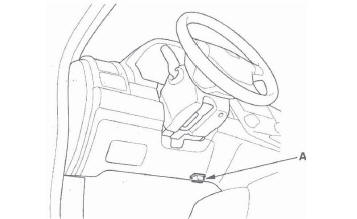
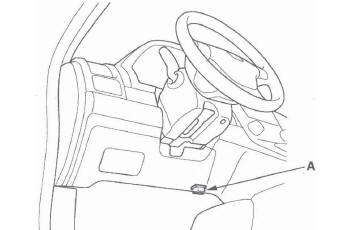
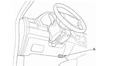
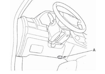
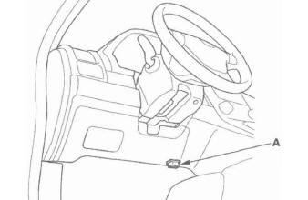
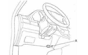
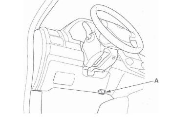
2. Connect the HDS to the DLC (A).
3. Turn the ignition switch ON (II).
4. Make sure the HDS communicates with the vehicle and the SRS unit. If it does not, troubleshoot the DLC circuit.
5. Use the HDS to check for DTCs.
6. Read and record the DTC.
7. Turn the ignition switch OFF, and wait for 10 seconds.
8. Disconnect the HDS from the DLC.
9. Do the troubleshooting procedure for the DTC.
Erasing the DTC Memory With the HDS
NOTE: Make sure the battery is fully charged before you begin.
1. Make sure the ignition switch is OFF.
2. Connect the HDS to the DLC (A).
3. Turn the ignition switch ON (II).
4. Make sure the HDS communicates with the vehicle and the SRS unit. If it does not, troubleshoot the DLC circuit.
5. In the SRS MENU of the HDS, select SRS, then DTC to erase DTC(s).
6. Turn the ignition switch OFF, and wait for 10 seconds.
7. Disconnect the HDS from the DLC.
Erasing the DTC Memory Using MES Connector Without the HDS
Special Tools Required
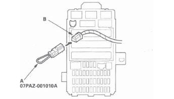
SCS Service Connector 07PAZ-001010A
NOTE: Make sure the battery is fully charged before you begin.
To erase the DTC(s) from the SRS unit, use the HDS or the following procedure.
1. Make sure the ignition switch is OFF.
2. Connect the SCS service connector (A) to the yellow MES 2P connector (B). Do not use a jumper wire.
3. Turn the ignition switch ON (II).
4. The SRS indicator will come on for about 6 seconds, and then go off. Remove the SCS service connector from the MES connector (2P) within 4 seconds after the indicator goes off.
5. The SRS indicator will come on again. Reconnect the SCS service connector to the MES connector (2P) within 4 seconds after the indicator comes on.
6, When the SRS indicator goes off, remove the SCS service connector from the MES connector (2P) within 4 seconds.
7. The SRS indicator blinks two times, indicating that the memory has been erased.
8. Turn the ignition switch OFF, and wait for 10 seconds.
9. Turn the ignition switch ON (II) again. If the SRS indicator comes on for 6 seconds, and then goes off, the system is OK.
Troubleshooting Intermittent Failures
If there was a malfunction that sets a DTC, but it does not recur, it will be stored in the memory as an intermittent failure, and the SRS indicator may come on depending on the malfunction detected.
NOTE: Check the condition of the battery, and the charging system. Low battery voltage may cause some intermittent failures.
After checking the DTC, troubleshoot as follows:
1. Read the DTC (see "Reading the DTC").
2. Erase the DTC memory (see "Erasing the DTC Memory").
3. Set the parking brake, then start the engine, and let it idle.
4. The SRS indicator comes on for about 6 seconds and then goes off.
5. Shake the related wire harnesses and the connectors, and look for loose connections, poor pinfits, and poor grounds.
6. Take a test-drive (quick acceleration, quick braking, and cornering), turn the steering wheel fully left and right, and hold it there for 5 to 10 seconds. If the problem recurs, the SRS indicator will come on.
NOTE: A faulty cable reel can cause intermittent connections related to the driver's airbag inflator DTCs.
7. If you cannot duplicate the concern, ask the customer about the conditions when it occured, or ask the customer to demonstrate the concern.
8. If you cannot duplicate the intermittent failure, the system is OK at this time.
Checking Seat Weight Sensors After a Vehicle Collision
1. Position the front passenger's seat to the rear most position, adjust the recliner to the most forward position. Do not move it from this position.
2. Drive the vehicle, accelerate to 20 mph (36 km/h), then stop on level ground.
3. Connect the HDS to the data link connector (DLC) (A).
4. From the SRS inspection menu, select Seat Weight Sensor, then Misc test, then "SEAT OUTPUT CHK" and follow the prompts until the ODS operation check has been completed.
ODS Unit Initialization
When a seat-back cover, seat-back cushion, and/or ODS unit is replaced, initialize the ODS by following the procedure.
NOTE: A new (uninitialized) ODS unit installed with a faulty OPDS sensor can cause DTC 85-71.
1. Erase the DTC memory.
2. Make sure the front passenger's seat is dry. Set the seat-back in a normal position, and make sure there is nothing on the seat.
3. Make sure the ignition switch is OFF and the MES connector is not shorted.
4. Connect the HDS to the DLC (A).
5. Turn the ignition switch ON (II).
6. Make sure the HDS communicates with the vehicle and the SRS unit. If it does not, troubleshoot the DLC circuit.
7. From the HDS Main Menu, select SRS, then SRS, then Calibration. In the Calibration Menu, select ODS INITIALIZATION. Follow the screen prompts to initialize the ODS.
8. Turn the ignition switch OFF.
9. Disconnect the HDS from the DLC.
NOTE: If the ODS system fails to initialize after several attempts, replace the OPDS sensor/seatback and retry. If the ODS system continues to fail to initialize, replace the ODS unit.
ODS Unit Calibration
When you replace the SRS unit, front passenger's weight sensors, or the ODS unit, calibrate the ODS unit.
While calibrating the ODS unit, observe these precautions:
- Make sure all components of the front passenger's seat are correctly installed.
- Make sure nothing is on or under the front passenger's seat.
- Make sure there is nothing in the front passenger's seat-back pocket.
- Keep the windows closed.
- Do all calibration procedures, except test-driving, in the service bay.
- Make sure the vehicle is on level ground.
- Keep the A/C and the heater off.
- Do not touch the front passenger's seat while you drive the vehicle.
- Do not expose the front passenger's seat to sudden temperature changes.
1. Position the front passenger's seat to the rearmost position, and adjust the recliner to the most forward position. Do not move the seat from these positions.
2. Connect the HDS to the data link connector (DLC) (A).
3. Make sure the HDS communicates with the vehicle and the SRS unit. If it does not, troubleshoot the DLC circuit.
4. Drive the vehicle, and accelerate to 20 mph (36 km/h), then stop on level ground.
5. From the Main Menu, select SRS, then Calibration, then Misc Test, then select "SWS INITIALIZATION," and follow the prompts until the initialization operation has been completed.
ODS Unit Operation Check
Check the ODS operation after any of these actions.
- Replacement of front passenger's seat component(s) (except ODS unit and/or weight sensors)
- After a vehicle collision
- SRS unit replacement
Pre-Operation Check Set-up
- Make sure all the components of the front passenger's seat are correctly installed.
- Position the front passenger's seat to the rearmost position. Adjust the seat recline to the forward most position. Do not move the seat from this position.
- Make sure nothing is on or under the front passenger's seat.
- Make sure there is nothing in the front passenger's seat-back pocket.
- Keep the windows closed.
- Do all calibration procedures, except test-driving, in the service bay.
- Make sure the vehicle is on level ground.
- Turn the heater and the A/C off.
- Do not touch the passenger's seat during the calibration.
- Do not expose the front passenger's seat to sudden temperature changes.
- Make sure all aftermarket devices such as a amplifiers, fluorescent lights, air purifiers, CB or HAM radios, etc, are turned off.
After Replacing Front Passenger's Seat Component(s)
1. Connect the HDS to the data link connector (DLC) (A).
2. Make sure the HDS communicates with the vehicle and the SRS unit. If it does not, troubleshoot the DLC circuit.
3. Drive the vehicle, accelerate to 20 mph (36 km/h), then stop on level ground.
4. From the HDS Main Menu, select SRS, then Inspection. In the HDS Inspection Menu, select "SEAT OUTPUT CHK" and follow the prompts until the ODS operation check has been completed.
Driver's Seat Position Sensor Operation Check
Check the driver's seat position after any of these actions.
- Driver's seat position sensor replacement
- Cover plate (front side of driver's seat slide rail) replacement
1. Make sure the driver's seat is at its full forward position.
2. Make sure the ignition switch is OFF (0).
3. Connect the HDS to the DLC (A).
4. Turn the ignition switch ON (II).
5. From the HDS Main Menu, select SRS, then Parameter Information, then Buckle Switch, Seat Position Sensor.
6. Using a piece of tape (A), mark the location on the seat's outer cover (B) where the front riser cover meets the seat riser (C). The driver's seat position sensor should read "NEAR."
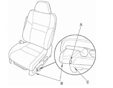
7. Move the seat back in small increments (about 0.2 in., 5 mm) until the driver's seat position sensor reads "NOT NEAR." The seat should be approximately 1 in. (25 mm) from the front.
NOTE: It takes a few seconds for the HDS to display changes, so wait about 5 seconds between each move.
If the driver's seat position sensor data does not work as described above, check the driver's seat position sensor or the cover plate for damage, and replace parts as needed.
8. Turn the ignition switch OFF, and disconnect the HDS from the DLC.
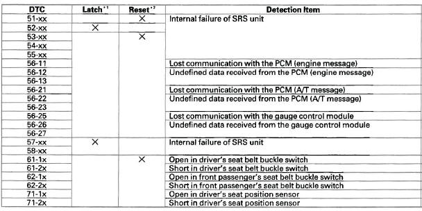
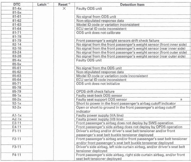
DTC Troubleshooting Index
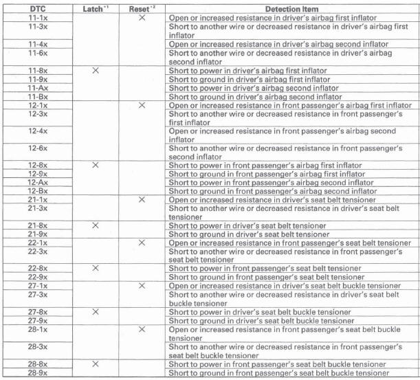
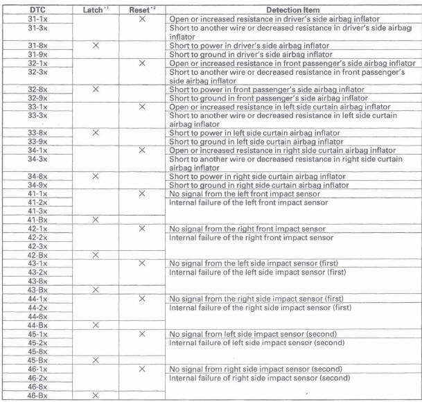
NOTE: The "x" at the end of each DTC denotes a numeric character (0 thru 9) or an alpha character (A thru F) that you will see on the HDS display. The character is unrelated to your troubleshooting; it designates the SRS unit manufacturer and other detail used for product analysis.
* 1: The SRS indicator turns on and stays on whenever the ignition switch is
in the ON (II) position, or until the code is cleared.
* 2: The SRS indicator turns on when the DTC is set. The SRS indicator will not
turn on after the ignition switch is cycled from ON (II) to OFF (0), but the DTC
will be stored in the SRS unit.
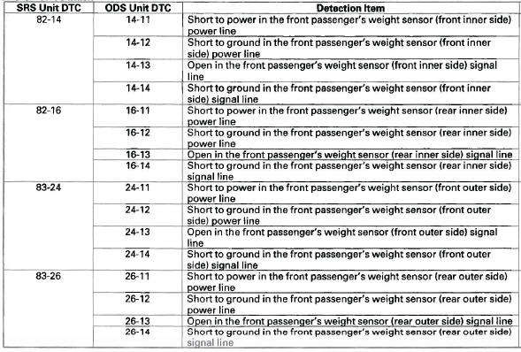
ODS Unit DTC Index
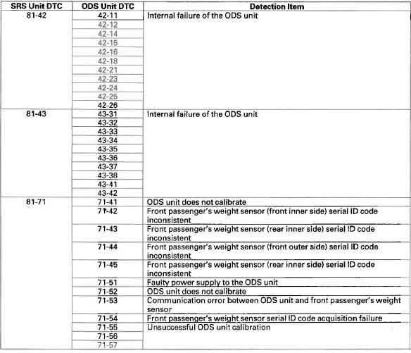
ODS Unit DTC Index
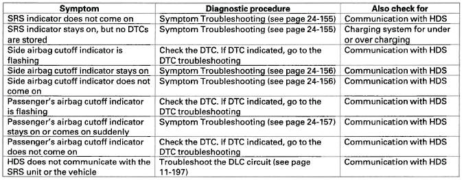
Symptom Troubleshooting Index
READ NEXT:
 System Description
SRS Components
Airbags
The SRS is a safety device which, when used with the seat belt, is designed
to help protect the driver and front
passenger in a frontal impact exceeding a certain set limit. Th
DTC 11-1x/4x ("x" can be 0 thru 9 or A thru F) :
Open or Increased Resistance in Driver's
Airbag First/Second Inflator
DTC 11-1x ("x" can be 0 thru 9 or A thru F):
Open or Increased Resistance in Driver's
Airbag First Inflator
DTC 11-4x ("x" can be 0 thru 9 or A thru F):
Open or Increased Resistance in Driver's
Airbag
SEE MORE:
A/T Interlock System
Component Location Index
DATA LINK CONNECTOR (DLC) SHIFT LOCK SOLENOID
Shift Lock System Circuit
Troubleshooting
Test
Replacement
PARK PIN SWITCH
Key Interlock System Circuit
Troubleshooting
Test
Replacement
STEERING LOCK ASSEMBLY KEY INTERLOCK SOLENOID
Key Interlock System Circuit Tro
Owner’s Maintenance Checks
You should check the following
items at the specified intervals. If
you are unsure of how to perform
any check, turn to the appropriate
page listed.
Engine oil level - Check every
time you fill the fuel tank.
Engine coolant level - Check the
radiator reserve tank every time
you fill
