Honda CR-V: DTC 51: Motor Locked
1. Turn the ignition switch ON (II).
2. Clear the DTC with the HDS.
3. Test-drive the vehicle. Drive the vehicle at 10 mph (15 km/h) or more, with the engine speed at 2,500 rpm or more.
4. Check for DTCs with the HDS.
Is DTC 51 indicated? YES-Replace the VSA modulator-control unit.
NO-Intermittent failure, the system is OK at this time. Check for a loose connection at G202.
DTC 52: Motor Stuck OFF
1. Turn the ignition switch OFF.
2. Check the No. 3 (40 A) fuse in the under-hood fuse/ relay box.
Is the fuse blown? YES-Go to step 3.
NO-Reinstall the checked fuse, then go to step 5.
3. Disconnect the VSA modulator-control unit 46P connector.
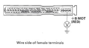
4. Check for continuity between VSA modulator-control unit 46P connector terminal No. 45 and body ground.
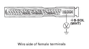
VSA MODULATOR-CONTROL UNIT 46P CONNECTOR
Is there continuity? YES-Repair short to body ground in the wire between the No.3 (40 A) fuse in the under-hood fuse/relay box and the VSA modulator-control unit.
NO-Install a new No.3 (40 A) fuse, then go to step 6.
5. Disconnect the VSA modulator-control unit 46P connector.
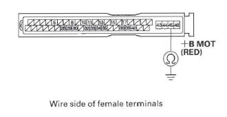
6. Measure the voltage between VSA modulator-control unit 46P connector terminal No. 45 and body ground.
VSA MODULATOR-CONTROL UNIT 46P CONNECTOR
Is there battery voltage? YES-Go to step 7.
NO-Repair open in the wire between the No. 3 (40 A) fuse in the under-hood fuse/relay box and the VSA modulator-control unit.
7. Reconnect the VSA modulator-control unit 46P connector.
8. Turn the ignition switch ON (II).
9. Clear the DTC with the HDS.
10. Test-drive the vehicle. Drive the vehicle at 10 mph (15 km/h) or more, with the engine speed at 2,500 rpm or more.
11. Check for DTCs with the HDS.
Is DTC 52 indicated? YES-Check for loose terminals in the VSA modulator-control unit 46P connector. Check for a loose connection at G202. If necessary, substitute a known-good VSA modulator-control unit and retest.
NO-Intermittent failure, the system is OK at this time. Check for loose terminals at the VSA modulator-control unit 46P connector. Check for a loose connection at G202. Refer to intermittent failures troubleshooting.
DTC 53: Motor Stuck ON
1. Turn the ignition switch ON (II).
Is the pump motor working? YES-Replace the VSA modulator-control unit.
NO-Go to step 2.
2. Turn the ignition switch OFF.
3. Disconnect the VSA modulator-control unit 46P connector.
4. Check for continuity between VSA modulator-control unit 46P connector terminal No. 46 and body ground.
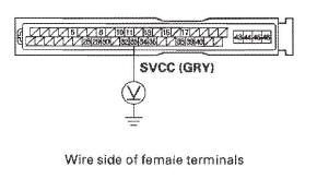
VSA MODULATOR-CONTROL UNIT 46P CONNECTOR
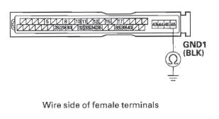
Is there continuity? YES-Go to step 5.
NO-Repair open in the wire between the VSA modulator-control unit and body ground (G202).
5. Reconnect the VSA modulator-control unit 46P connector.
6. Turn the ignition switch ON (II).
7. Clear the DTC with the HDS.
8. Test-drive the vehicle. Drive the vehicle at 10 mph (15 km/h) or more, and the engine speed is 2,500 rpm or more.
9. Check for DTCs with the HDS.
Is DTC 53 indicated? YES-Check for loose terminals in the VSA modulator-control unit 46P connector. Check for a loose connection at G202. If necessary, substitute a known-good VSA modulator-control unit and retest.
NO-Intermittent failure, the system is OK at this time. Check for loose terminals at the VSA modulator-control unit 46P connector. Check for a loose connection at G202. Refer to intermittent failures troubleshooting.
DTC 54: Valve Relay
1. Turn the ignition switch OFF.
2. Check the No.3 (20 A) fuse in the under-hood fusel relay box.
Is the fuse blown? YES-Go to step 3.
NO-Reinstall the checked fuse, then go to step 5.
3. Disconnect the VSA modulator-control unit 46P connector.
4. Check for continuity between VSA modulator-control unit 46P connector terminal No. 44 and body ground.
VSA MODULATOR-CONTROL UNIT 46P CONNECTOR
Is there continuity? YES-Repair short to body ground in the wire between the No.3 (20 A) fuse in the under-hood fuse/relay box and the VSA modulator-control unit.
NO-Install a new No.3 (20 A) fuse, then go to step 6.
5. Disconnect the VSA modulator-control unit 46P connector.
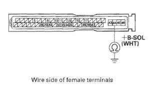
6. Measure the voltage between VSA modulator-control unit 46P connector terminal No. 44 and body ground.
VSA MODULATOR-CONTROL UNIT 46P CONNECTOR
Is there battery voltage? YES-Go to step 7.
NO-Repair open in the wire between the No.3 (20 A) fuse in the under-hood fuse/relay box and the VSA modulator-control unit.
7. Reconnect the VSA modulator-control unit 46P connector.
8. Turn the ignition switch ON (II).
9. Clear the DTC with the HDS.
10. Turn the ignition switch OFF, then turn it ON (II) again.
11. Check for DTCs with the HDS.
Is DTO 54 indicated? YES-Check for loose terminals in the VSA modulator-control unit 46P connector. Check for a loose connection at G202. If necessary, substitute a known-good VSA modulator-control unit. and retest.
NO-Intermittent failure, the system is OK at this time. Check for loose terminals at the VSA modulator-control unit 46P connector. Check for a loose connection at G202. Refer to intermittent failures troubleshooting.
DTC 61: IG1 Voltage Low
1. Turn the ignition switch ON (II).
2. Clear the DTC with the HDS.
3. Test-drive the vehicle at 2 mph (3 km/h) or more.
4. Check for DTCs with the HDS.
Is DTO 61 indicated? YES-Go to step 5.
NO-Intermittent failure, the system is OK at this time. Check for loose terminals at the VSA modulator-control unit 46P connector. Check for a loose connection at G202. Refer to intermittent failures troubleshooting.
5. Test the battery and check the connections.
Are the battery and battery connections OK? YES-Check for a poor connection at the battery terminals, and all lG1 circuit connections between the VSA modulator-control unit 46P connector terminal No. 40 and the under-dash fuse/relay box NO.4 (7.5 A) fuse. Check for a loose connection at G202. If the connections are good, go to the Alternator and Regulator Circuit Troubleshooting.
NO-Replace or charge the battery, or repair the connections.
DTC 62: IG1 Voltage High
NOTE: An overcharging alternator can cause this DTC.
1. Turn the ignition switch ON (II).
2. Clear the DTC with the HDS.
3. Test-drive the vehicle at 2 mph (3 km/h) or more.
4. Check for DTCs with the HDS.
Is DTC 62 indicated? YES-Check for a poor connection at the battery terminals. Check for a loose connection at G202. If the connections are good, go to the Alternator and Regulator Circuit Troubleshooting. NO-Intermittent failure, the system is OK at this time. Check for loose terminals at the VSA modulator-control unit 46P connector. Check for a loose connection at G202. Refer to intermittent failures troubleshooting.
DTC 64: Steering Angle Sensor (Power Supply)
1. Turn the ignition switch ON (II).
2. Clear the DTC with the HDS.
3. Turn the ignition switch OFF, then turn it ON (II) again.
4. Check for DTCs with the HDS.
Is DTC 64 indicated? YES-Go to step 5.
NO-Intermittent failure. the system is OK at this time. Check for loose terminals at the VSA modulator-control unit 46P connector. Check for a loose connection at G202. Refer to intermittent failures troubleshooting.
5. Turn the ignition switch OFF.
6. Disconnect the VSA modulator-control unit 46P connector.
7. Turn the ignition switch ON (II).
8, Measure the voltage between VSA modulator-control unit 46P connector terminal No. 33 and body ground.
VSA MODULATOR-CONTROL UNIT 46P CONNECTOR
Is there battery voltage? YES-Repair short to power in the wire between the VSA modulator-control unit and the steering angle sensor.
NO-Go to step 9.
9. Turn the ignition switch OFF.
10. Check for continuity between VSA modulator-control unit 46P connector terminal No. 33 and body ground.
VSA MODULATOR-CONTROL UNIT 46P CONNECTOR
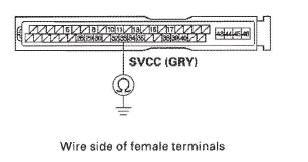
Is there continuity? YES-Repair short to body ground in the wire between the VSA modulator-control unit and the steering angle sensor.
NO-Go to step 11.
11. Reconnect the VSA modulator-control unit 46P connector.
12. Disconnect the steering angle sensor 5P connector.
13. Turn the ignition switch ON (II).
14. Measure the voltage between steering angle sensor 5P connector terminals No.1 and No.5.
STEERING ANGLE SENSOR 5P CONNECTOR
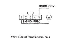
Is there 5 V? YES-Replace the steering angle sensor.
NO-Check for loose terminals in the VSA modulator-control unit 46P connector. Check for a loose connection at G202. If necessary, substitute a known-good VSA modulator-control unit (see page 19-97) and retest.
DTC 66: VSA Pressure Sensor (Hardware)
1. Turn the ignition switch ON (II).
2. Clear the DTC with the HDS.
3. Turn the ignition switch OFF, then turn it ON (II) again.
4. Check for DTCs with the HDS.
Is DTC 66 indicated? YES-Replace the VSA modulator-control unit.
NO-Intermittent failure, the system is OK at this time. Check for a loose connection at G202.
DTC 68: Brake Pedal Position Switch Stuck ON (Hardware)
1. Turn the ignition switch ON (II).
2. Check for DTCs with the HDS.
Is DTC 86 indicated with DTC 68 at the same time? YES-Do the DTC 86 troubleshooting.
NO-Go to step 3.
3. Check the BRAKE SWITCH in the VSA DATA LIST with the HDS while moving the brake pedal.
Does it indicate ON when the pedal is pressed, and OFF when the pedal is released? YES-Go to step 4.
NO-Go to step 7.
4. Clear the DTC with the HDS.
5. Test-drive the vehicle at 10 mph (15 km/h) for 60 seconds or more.
6. Check for DTCs with the HDS.
Is DTC 68 indicated? YES- Check for loose terminals in the VSA modulator-control unit 46P connector. Check for a loose connection at G202. If necessary, substitute a know-good VSA modulator-control unit and retest.
NO-Intermittent failure, the system is OK at this time. Check for loose terminals at the VSA modulator-control unit 46P connector. Check for a loose connection at G202. Refer to intermittent failures troubleshooting.
7. Turn the ignition switch OFF.
8. Disconnect the brake pedal position switch 4P connector.
9. Do the brake pedal position switch test.
Is the switch OK? YES- Check the fuel and emissions systems, and troubleshoot the brake pedal position switch signal circuit.
NO-Replace the brake pedal position switch.
DTC 81: Central Processing Unit (CPU)
1. Turn the ignition switch ON (II).
2. Clear the DTC with the HDS.
3. Turn the ignition switch OFF, then turn it ON (II) again.
4. Check for DTCs with the HDS.
Is DTC 81 indicated? YES-Replace the VSA modulator-control unit.
NO-Intermittent failure, the system is OK at this time. Check for loose terminals in the VSA modulator-control unit 46P connector. Check for a loose connection at G202.
DTC 83: PCM Communication Error
1. Turn the ignition switch ON (II).
2. Check for DTCs with the HDS.
Is DTC 86 indicated with DTC 83 at the same time? YES-Do the DTC 86 troubleshooting.
NO-Go to step 3.
3. Check for the fuel and emissions systems DTCs with the HDS.
Are any DTCs indicated? YES-Do the applicable troubleshooting for the PCM.
NO-Go to step 4.
4. Clear the DTC with the HDS.
5. Turn the ignition switch OFF, then turn it ON (II) again.
6. Check for DTCs with the HDS.
Is DTC 83 indicated? YES-Check for loose terminals in the VSA modulator-control unit 46P connector. Check for a loose connection at G202. If necessary, substitute a known-good VSA modulator-control unit and retest.
NO-Intermittent failure, system is OK at this time.
Check for loose terminals between the PCM connector A (44P), and the VSA modulator-control unit 46P connector. Check for a loose connection at G202. Refer to intermittent failures troubleshooting.
READ NEXT:
 DTC 86: F-CAN Communication
1. Turn the ignition switch ON (II).
2. Clear the DTC with the HDS.
3. Turn the ignition switch OFF.
4. Start the engine.
5. Wait at least 5 seconds.
6. Check for DTCs with the HDS.
Is DTC 86 in
DTC 91: VSA System
1. Check the brake system for leaks or mechanical
problems.
Is the brake system OK? (No brake fluid leakage,
no air trapped in the brake system, no brake pads
worn out.)
YES-Go to step 2.
NO-Repair
Symptom Troubleshooting
VSA activation indicator does not go off, and
no DTCs are stored
1. Turn the ignition switch ON (II), and watch the VSA
activation indicator.
Does VSA activation indicator go off within 2 seconds? YE
SEE MORE:
Entry Lights Control System
Component Location Index
With moonroof
INDIVIDUAL MAP LIGHTS
IGNITION KEY SWITCH
IGNITION KEY LIGHT
CEILING LIGHT
CARGO AREA LIGHT
RIGHT REAR DOOR SWITCH
FRONT PASSENGER'S
DOOR SWITCH
LEFT REAR DOOR SWITCH
DRIVER'S DOOR
SWITCH
DRIVER'S DOOR
LOCK KNOB SWITCH
MICU (Built into the under
Tailgate
Tailgate Adjustment
NOTE:
Have an assistant help you when adjusting the
tailgate.
Take care not to scratch the tailgate, body, and other
related parts.
Put on gloves to protect your hands.
1. Remove these items:
Quarter pillar glass trim, both sides
Tailgate weatherstrip, as needed
Cargo
