Honda CR-V: DTC 91: VSA System
1. Check the brake system for leaks or mechanical problems.
Is the brake system OK? (No brake fluid leakage, no air trapped in the brake system, no brake pads worn out.) YES-Go to step 2.
NO-Repair the brake system, then recheck.
2. Turn the ignition switch ON (II).
3. Clear the DTC with the HDS.
4. Test-drive the vehicle in a straight line. Accelerate the vehicle up to 6 mph (10 km/h), and stop, then accelerate up to 6 mph (10 km/).
5. Check for DTCs with the HDS.
Is DTC 91 indicated? YES-Check for loose terminals in the VSA modulator-control unit 46P connector. Check for a loose connection at G202. If necessary, substitute a known-good VSA modulator-control unit and retest.
NO-Intermittent failure, the system is OK at this time. Check for loose terminals at the VSA modulator-control unit 46P connector. Check for a loose connection at G202. Refer to intermittent failures troubleshooting.
DTC 113: Yaw Rate-lateral Acceleration Sensor (Power Supply)
1. Turn the ignition switch OFF.
2. Disconnect the yaw rate-lateral acceleration sensor 4P connector.
3. Turn the ignition switch ON (II).
4. Measure the voltage between body ground and yaw rate-lateral acceleration sensor 4P connector terminal No.1.
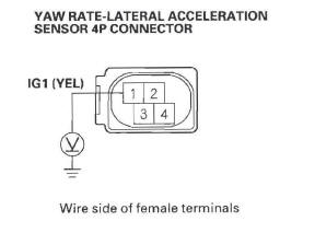
Is there battery voltage? YES-Replace the yaw rate-lateral acceleration sensor.
NO-Repair open in the wire between the No.4 (7.5 A) fuse in the under-dash fuse/relay box and the yaw rate-lateral acceleration sensor.
DTC 114: Yaw Rate-Lateral Acceleration Sensor Installation Problem
1. Turn the ignition switch ON (II).
2. Clear the DTC with the HDS.
3. Turn the ignition switch OFF, then turn it ON (II) again.
4. Check for DTCs with the HDS.
Is DTG 114 indicated? YES-Replace the yaw rate-lateral acceleration sensor.
NO-Intermittent failure, the system is OK at this time. Check for loose terminals at the yaw rate-lateral acceleration sensor 4P connector. Check for a loose connection at G552. Refer to intermittent failures troubleshooting.
DTC 121, 122, 123, 124: VSA Solenoid
1. Turn the ignition switch ON (II).
2. Clear the DTC with the HDS.
3. Turn the ignition switch OFF, then turn it ON (II) again.
4. Check for DTCs with the HDS.
Is DTG 121, 122, 123, and/or 124 indicated? YES-Replace the VSA modulator-control unit.
NO-Intermittent failure, the system is OK at this time. Check for a loose connection at G202.
DTC 131: Yaw Rate Sensor (Software)
NOTE: Driving on an extremely angled road can cause this DTC.
1. Turn the ignition switch ON (II).
2. Check for DTCs with the HDS.
Is DTC 91 indicated with DTC 131 at the same time? YES-Do the DTC 91 troubleshooting.
NO-Go to step 3.
3. Turn the ignition switch OFF.
4. Check that the yaw rate-lateral acceleration sensor is properly mounted.
Is the yaw rate-lateral acceleration sensor installation OK? YES-Go to step 5.
NO-Reinstall the yaw rate-lateral acceleration sensor, and recheck by test-driving.
5. Put the vehicle on a level surface.
6. Turn the ignition switch ON (II).
7. Check the YAW RATE S in the VSA DATA LIST with the HDS.
Is the indicated value within +-5 º/s? YES-Go to step 8.
NO-Replace the yaw rate-lateral acceleration sensor.
8. Clear the DTC with the HDS.
9. Test-drive the vehicle around a number of corners.
10. Check for DTCs with the HDS.
Is DTC 131 indicated? YES-Go to step 11.
NO-Intermittent failure; the most probable cause is that the vehicle has been driven on an extremely angled road. The system is OK at this time.
11. Turn the ignition switch OFF.
12. Substitute a known-good yaw rate-lateral acceleration sensor.
13. Turn the ignition switch ON (II).
14. Clear the DTC with the HDS.
15. Test-drive the vehicle around a number of corners.
16. Check for DTCs with the HDS.
Is DTC 131 indicated? YES-Replace the VSA modulator-control unit.
NO-Replace the original yaw rate-lateral acceleration sensor.
DTC 132: Lateral Acceleration Sensor (Software)
DTC 133: Lateral Acceleration Sensor (Joint Failure)
NOTE: Driving on an extremely angled road can cause this DTC.
1. Turn the ignition switch ON (II).
2. Check for DTCs with the HDS.
Is DTC 91 indicated with DTC 132 or 133 at the same time? YES - Do the DTC 91 troubleshooting.
NO- Go to step 3.
3. Turn the ignition switch OFF.
4. Check that the yaw rate-lateral acceleration sensor is properly mounted.
Is the yaw rate-lateral acceleration sensor installation OK? YES- Go to step 5.
NO-Reinstall the yaw rate-lateral acceleration sensor, and recheck by test-driving.
5. Put the vehicle on a level surface.
6. Turn the ignition switch ON (II).
7. Check the LATERAL ACCELERATION SENSOR in the VSA DATA UST with the HDS.
Is the indicated within +- 1 m/s? YES - Go to step 8.
NO-Replace the yaw rate-lateral acceleration sensor.
8. Clear the DTC with the HDS.
9. Test-drive the vehicle around a number of corners.
10. Check tor DTCs with the HDS.
Is DTC 132 or 133 indicated? YES-Go to step 11.
NO-Intermittent failure; the most probable cause is that the vehicle has been driven on an extremely angled road. The system is OK at this time.
11. Turn the ignition switch OFF.
12. Substitute a known-good yaw rate-lateral acceleration sensor.
13. Turn the ignition switch ON (II).
14. Clear the DTC with the HDS.
15. Test-drive the vehicle around a number of corners.
16. Check for DTCs with the HDS.
Is DTC 132 or 133 indicated? YES-Replace the VSA modulator-control unit.
NO-Replace the original yaw rate-lateral acceleration sensor.
DTC 134: Steering Angle Sensor (Software)
1. Turn the ignition switch ON (II).
2. Check for DTCs with the HDS.
Is DTC 91 indicated with DTC 134 at the same time? YES-Do the DTC 91 troubleshooting.
NO-Go to step 3.
3. With the vehicle on the ground, set the front wheels in the straight ahead driving position.
4. Check Z-PHASE in the VSA DATA LIST with the HDS.
Is there about 1.0 V or less with the steering wheel straight ahead? YES - Go to step 5.
NO-Go to step 7.
5. Start the engine.
6. Turn the steering wheel left and right at 90 degrees or more. Check the STEERING ANGLE in the VSA DATA LIST with the HDS.
Is there +-90 º or more? YES-Go to step 1.
NO- Replace the steering angle sensor.
1. Turn the ignition switch OFF.
8. Check the installation of the steering angle sensor.
Is the steering angle sensor installed correctly? YES-Go to step 15.
NO-Go to step 9.
9. Reinstall the steering angle sensor.
10. Turn the ignition switch ON (II).
11. Clear the DTCs with the HDS.
12. Test-drive the vehicle around a number of corners.
13. Check for DTCs with the HDS.
Is DTC 134 indicated? YES-Go to step 14.
NO- The system is OK at this time.
14. Turn the ignition switch OFF.
15. Substitute a known-good steering angle sensor.
16. Turn the ignition switch ON (II).
17. Clear the DTCs with the HDS.
18. Test-drive the vehicle around a number of corners.
19. Check for DTCs with the HDS.
Is DTC 134 indicated? YES-Check for loose terminals in the VSA modulator-control unit 46P connector. Check for a loose connection at G202. If necessary, substitute a known-good VSA modulator-control unit and retest. NO- Replace the original steering angle sensor.
DTC 137: VSA Pressure Sensor (Software)
1. Turn the ignition switch OFF (II).
2. Disconnect the brake pedal position switch 4P connector.
3. Do the brake pedal position switch test.
Is the switch OK? YES-Go to step 4.
NO-Replace the brake pedal position switch.
4. Short the SCS line with the HDS.
5. Disconnect the PCM connector A (44P).
6. Turn the ignition switch ON (II).
7. Measure the voltage between PCM connector A (44P) terminal No. 40 and body ground.
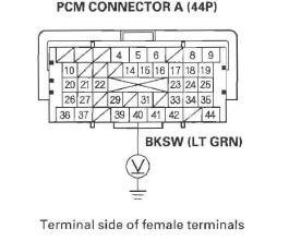
Is there 0.1 V or more when the brake pedal released? YES-Repair short to power in the wire between the brake pedal position switch and the PCM.
NO-Go to step 8.
8. Turn the ignition switch OFF.
9. Substitute a known-good PCM.
10. Turn the ignition switch ON (II).
11. Clear the DTCs with the HDS.
12. Test-drive the vehicle at 8 mph (12 km/h) for 60 seconds or more.
13. Check for DTCs with the HDS.
Is DTC 137 indicated? YES-Check for loose terminals in the VSA modulator-control unit 46P connector. Check for a loose connection at G202. If necessary, substitute a known-good VSA modulator-control unit and retest.
NO-Replace the original PCM.
DTC 138: Brake Pedal Position Switch Stuck OFF (Software)
1. Turn the ignition switch OFF.
2. Check the No. 12 (15 A) fuse in the under-hood fuse/relay box.
Is the fuse OK? YES-Reinstall the fuse, and go to step 3.
NO-Replace the fuse, and recheck. If the fuse is blown, check for a short to body ground in the brake pedal position switch circuit.
3. Disconnect the brake pedal position switch 4P connector.
4. Measure the voltage between brake pedal position switch 4P connector terminal No.1 and body ground.
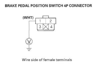
Is there battery voltage? YES-Go to step 5.
NO-Repair open in the wire between the No. 12 (15 A) fuse in the under-hood fuse/relay box and the brake pedal position switch.
5. Short the SCS line with the HDS.
6. Disconnect the PCM connector A (44P).
7. Check for continuity between brake pedal position switch 4P connector terminal No.2 and PCM connector A (44P) terminal No. 40.
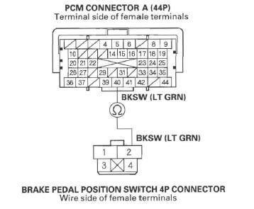
Is there continuity? YES-Go to step 8.
NO-Repair open in the wire between the PCM and the brake pedal position switch.
8. Do the brake pedal position switch test.
Is the switch OK? YES-Go to step 9.
NO-Replace the brake pedal position switch.
9. Substitute a known-good PCM.
10. Start the engine, then press the brake pedal slowly and hard.
11. Check for DTCs with the HDS.
Is DTC 138 indicated? YES-Check for loose terminals in the VSA modulator-control unit 46P connector. Check for a loose connection at G202. If necessary, substitute a known-good VSA modulator-control unit and retest.
NO-Replace the original PCM.
READ NEXT:
 Symptom Troubleshooting
VSA activation indicator does not go off, and
no DTCs are stored
1. Turn the ignition switch ON (II), and watch the VSA
activation indicator.
Does VSA activation indicator go off within 2 seconds? YE
Steering Angle Sensor Replacement
NOTE: Do not damage or drop the combination switch as the steering angle
sensor is sensitive to shock and vibration.
1. Remove the steering wheel.
2. Remove the steering column covers and the cable
SEE MORE:
Reporting Safety Defects (U.S. Vehicles)
If you believe that your vehicle has a
defect which could cause a crash or
could cause injury or death, you
should immediately inform the
National Highway Traffic Safety
Administration (NHTSA) in addition
to notifying American Honda Motor
Co., Inc.
If NHTSA receives similar complaints
Symptom Troubleshooting
Power Door Locks/Keyless
1. Check for B-CAN DTCs. If any B-CAN DTCs are indicated, troubleshoot and
resolve them first.
2. If the door lock system and the keyless operation. does not work, troubleshoot
the door locks first.
NOTE: The system does not function when the ignition switch is ON (II).
