Honda CR-V: DTC 86: F-CAN Communication
1. Turn the ignition switch ON (II).
2. Clear the DTC with the HDS.
3. Turn the ignition switch OFF.
4. Start the engine.
5. Wait at least 5 seconds.
6. Check for DTCs with the HDS.
Is DTC 86 indicated? YES-Go to step 7.
NO-Intermittent failure, the system is OK at this time. Check for a loose connection at G202.
7. Check for the fuel and emissions systems DTCs with the HDS.
Are any DTCs indicated? YES-Do the applicable troubleshooting for the PCM.
NO- Go to step 8.
8. Turn the ignition switch OFF.
9. Disconnect the yaw rate-lateral acceleration sensor 4P connector.
10. Turn the ignition switch ON (II).
11. Measure the voltage between yaw rate-lateral acceleration sensor 4P connector terminal No.1 and body ground.
YAW RATE-LATERAL ACCELERATION SENSOR 4P CONNECTOR
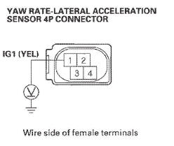
Is there battery voltage? YES-Go to step 12.
NO-Repair open in the wire between No.4 (7.5 A) fuse in the under-dash fuse/relay box and the yaw rate-lateral acceleration sensor.
12. Turn the ignition switch OFF.
13. Check for continuity between yaw rate-lateral acceleration sensor 4P connector terminal No.4 and body ground.
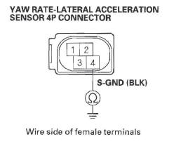
Is there continuity? YES-Go to step 14.
NO-Repair open in the wire between the yaw rate-lateral acceleration sensor and body ground (G552).
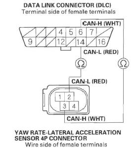
14. Check for continuity between the appropriate DLC terminals and yaw rate-lateral acceleration sensor 4P connector terminals respectively (see table).
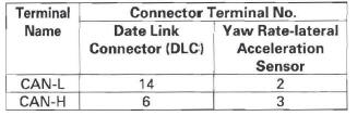
Is there continuity? YES-Go to step 15.
NO-Repair open in the wire between DLC and the yaw rate-lateral acceleration sensor.
15. Disconnect the VSA modulator-control unit 46P connector.
16. Check for continuity between the appropriate VSA modulator-control unit 46P connector terminals and DLC terminals respectively (see table).
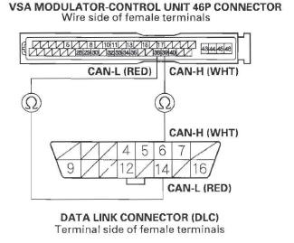
Is there continuity? YES-Go to step 17.
NO-Repair open in the wire between VSA modulator-control unit and DLC.
17. Connect the VSA modulator-control unit 46P connector.
18. Turn the ignition switch ON (II).
19. Clear the DTC with the HDS.
20. Turn the ignition switch OFF.
21. Start the engine.
22. Wait at least 5 seconds.
23. Check for DTCs with the HDS.
Is DTC 86 indicated? YES-Replace the VSA modulator-control unit.
NO-The system is OK at this time.
DTC 87: Current Flow into Wheel Sensor Input Amplifier
1. Turn the ignition switch ON (II).
2. Clear the DTC with the HDS.
3. Turn the ignition switch OFF, then turn it ON (II) again.
4. Check for DTCs with the HDS.
Is DTC 87 indicated? YES-Dothe DTC 11, 13, 15, and/or 17 troubleshooting.
NO-Intermittent failure, the system is OK at this time. Check for loose terminals between the wheel sensor 2P connector and the VSA modulator-control unit 46P connector. Check for a loose connection at G202. Refer to intermittent failures troubleshooting.
DTC 88: Difference in Wheel Speed
NOTE: A wheel bearing that is installed backwards can cause this DTC.
1. Check all four tires.
Are all four tires the correct size and properly inflated? YES-Go to step 2.
NO-Install the correct tires, a known-good set of tires, or set the tires to the correct pressure, and retest by test-driving.
2. Test drive the vehicle.
3. Check the RF, LF, RR, LR, WHEEL SPD in the VSA DATA LIST with the HDS.
Are all four the same indicated value? YES-Go to step 4.
NO-Reinstall or replace the wheel sensor(s) (see page 19-99), and recheck by test-driving.
4. Check the magnetic encoders on the front wheel bearings (see page 18-12) or rear magnetic encoders on the hub bearing units.
Are they installed correctly and in good condition? YES-Check for loose terminals in the VSA modulator-control unit 46P connector. Check for a loose connection at G202. If necessary, substitute a known-good VSA modulator-control unit (see page 19-97) and retest.
NO-Replace the front wheel bearing(s) or the rear hub bearing unit(s) and recheck by test-driving:
- Front: Replace the front wheel bearing.
- Rear: Replace the rear hub bearing unit.
READ NEXT:
 DTC 91: VSA System
1. Check the brake system for leaks or mechanical
problems.
Is the brake system OK? (No brake fluid leakage,
no air trapped in the brake system, no brake pads
worn out.)
YES-Go to step 2.
NO-Repair
Symptom Troubleshooting
VSA activation indicator does not go off, and
no DTCs are stored
1. Turn the ignition switch ON (II), and watch the VSA
activation indicator.
Does VSA activation indicator go off within 2 seconds? YE
Steering Angle Sensor Replacement
NOTE: Do not damage or drop the combination switch as the steering angle
sensor is sensitive to shock and vibration.
1. Remove the steering wheel.
2. Remove the steering column covers and the cable
SEE MORE:
Installing a Child Seat with LATCH
Your vehicle is equipped with
LATCH (Lower Anchors and
Tethers for CHildren) at the rear
seats to secure a child seat in any
seating position: one in each outer
seating position, or one in the center.
The five lower anchors are located
between the seat-back and seat
bottom, and are to
Windshield Replacement
NOTE:
Put on gloves to protect your hands.
Wear eye protection when removing the glass with
piano wire.
Use seat covers to avoid damaging the seat.
When replacing a broken windshield, a commercially
available windshield cutter can be efficiently used for
cutting the adhesive. Follow the equi
