Honda CR-V: System Description
SRS Components
Airbags
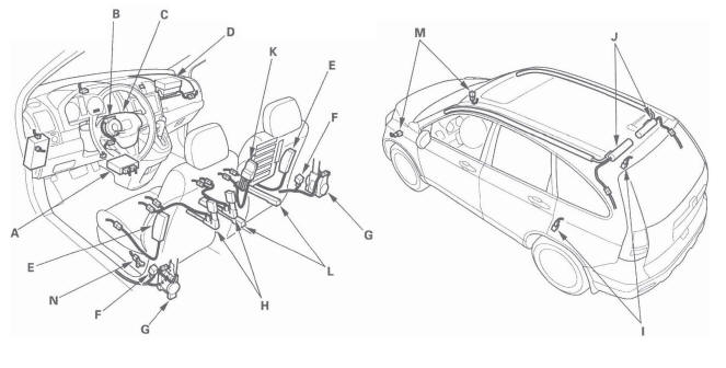
The SRS is a safety device which, when used with the seat belt, is designed to help protect the driver and front passenger in a frontal impact exceeding a certain set limit. The system consists of the SRS unit, including safing sensor and impact sensor (A), the cable reel (B), the driver's airbag (C), the front passenger's airbag (D), side airbags (E), side curtain airbags (J), seat belt tensioners (G), seat belt buckle tensioners (H), side impact sensors (first) (F), front impact sensors (M) and side impact sensors (second) (I).
Since the driver's and front passenger's airbags use the same sensors, both normally inflate at the same time.
However, it is possible for only one airbag to inflate. This can occur when the severity of a collision is at the margin, or threshold, that the SRS unit determines whether or not the airbags will deploy. In such cases, the seat belt will provide sufficient protection, and the supplemental protection offered by the airbag would be minimal.
Front Passenger's Weight Sensors
The ODS unit (K) is in the front passenger's seat-back. The seat weight sensors (L) are part of the seat base. The weight sensors detect the weight on the seat, and send the information to the ODS unit. If the total weight is about 65 Ibs (30 kg) or less, the ODS unit sends a signal to the SRS unit to prevent the front passenger's airbag from deploying.
When the front passenger's airbag is disabled, the passenger airbag cutoff indicator on the center panel comes on to alert the driver that the front passenger's airbag will not deploy in a front-end collision.
Driver's Seat Position Sensor
The driver's seat position sensor (N) is under the driver's seat on the left side. When the driver's seat is moved to its full forward position, the deployment of the driver's airbag is moderated to decrease its force of impact during a front-end collision.
Side Airbag Cutoff Indicator/ODS Operation
The indicator comes on if the front passenger's seat is occupied by a small adult or child who is leaning into the deployment path, or an object (grocery bag, briefcase, purse, etc.) is in the seat. When the indicator comes on, the passenger's side airbag is off and will not deploy; there is no problem with the side airbag. If the passenger sits upright or moves to another seat, or you remove the object from the seat, the light should go off. There will be some delay between the occupant's repositioning, and when the indicator will turn on or off.
Passenger Airbag Cutoff Indicator
The indicator comes on if the weight of the front passenger is about 65 Ibs (30 kg) or less. This indicates the passenger's front airbag is off and will not deploy. The front airbag is shut off to reduce the chance of airbag-caused injuries.
SRS Operation
The main circuit in the SRS unit senses and judges the force of impact and, if necessary, ignites the inflator charges. If battery voltage is too low or power is disconnected due to the impact, the voltage regulator and the back-up power circuit will keep voltage at a constant level.
For the SRS to operate
Seat Belt Tensioners and Seat Belt Buckle Tensioners
- A front impact sensor, or side impact sensor, must activate and send electric signals to the microprocessor.
- The microprocessor must compute the signals and send them to the tensioners.
- The charges must ignite and deploy the tensioners.
Driver's and Front Passenger's Airbag(s)
- A front impact sensor must activate, and send electric signals to the microprocessor.
- The microprocessor must compute the signals, and send them to the airbag inflator(s).
- The inflators that received signals must ignite and deploy the airbags.
Side Airbag(s)
- A side impact sensor must activate, and send electric signals to the microprocessor.
- The microprocessor must compute the signals and send them to the side airbag inflator(s). However, the microprocessor cuts off the signals to the front passenger's side airbag if the SRS unit determines that the front passenger's head is in the deployment path of the side airbag.
- The inflator that received the signal must ignite and deploy the side airbag.
Side Curtain Airbag(s)
- Side impact sensor must activate, and send electrical signals to the microprocessor.
- The microprocessor must compute the signals and send them to the side curtain airbag and side airbag inflator(s).
- The inflator that received the signals must ignite and deploy the side curtain airbag and side airbag at the same time.
Self-diagnostic System
A self-diagnostic circuit is built into the SRS unit; when the ignition switch is turned ON (II), the SRS indicator comes on and goes off after about 6 seconds if the system is operating normally.
If the indicator does not come on, or does not go off after 6 seconds, or if it comes on while driving, it indicates an abnormality in the system. The system must be inspected and repaired as soon as possible.
For better serviceability, the SRS unit memory stores a DTC that relates to the cause of the malfunction, and the unit is connected to the data link connector (DLC). This information can be read with the HDS when it is connected to the DLC (16P).
NOTE: Before you disconnect the negative cable from the battery for troubleshooting, make sure you have the antitheft code for the audio or the navigation system (if equipped). Write down the XM audio presets (if equipped).
SRS Unit Inputs and Outputs at Connector A (28P)
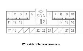
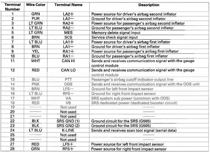
NOTE: BLU or BRN wires may be substituted for the wire colors In this table.
SRS Unit Inputs and Outputs at Connector B (28P)
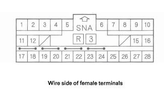
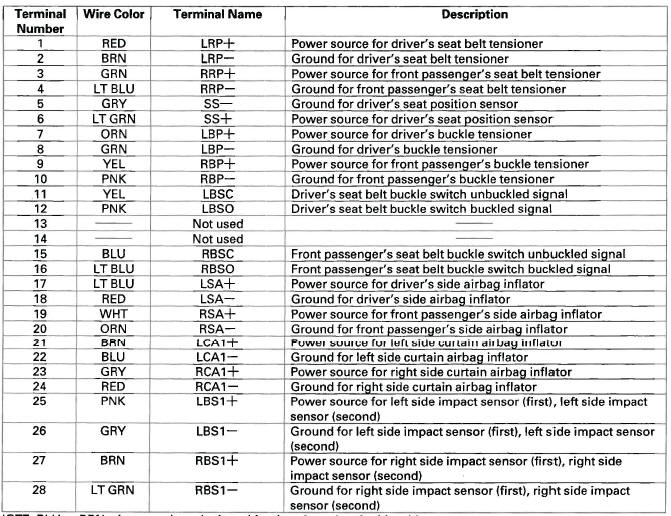
NOTE: BLU or BRN wires may be substituted for the wire colors in this table.
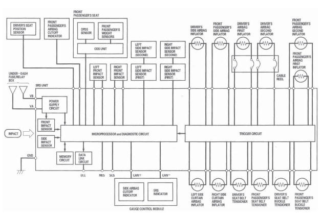
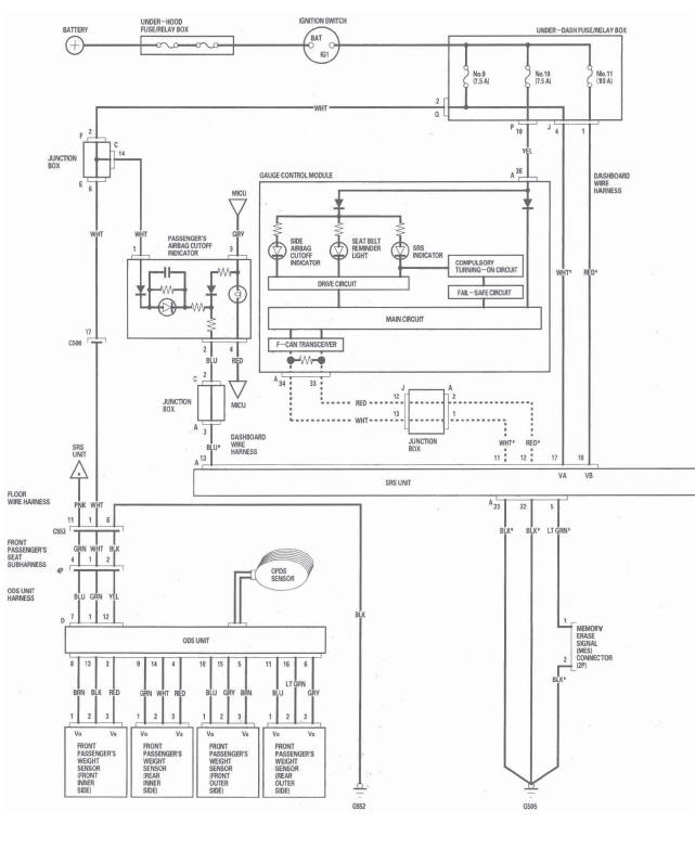
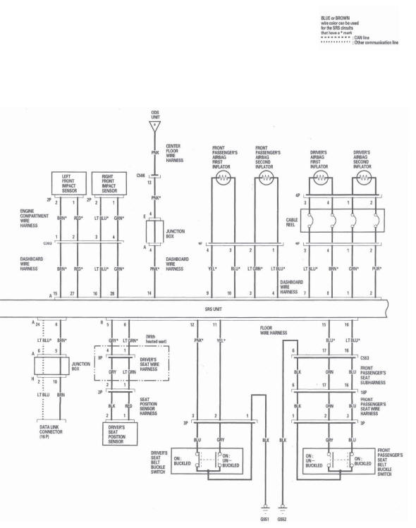
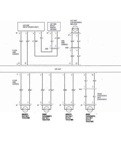
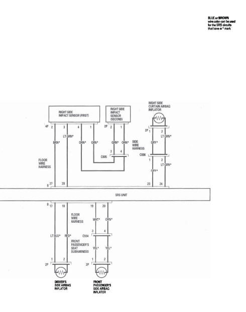
Circuit Diagram
READ NEXT:
 DTC 11-1x/4x ("x" can be 0 thru 9 or A thru F) :
Open or Increased Resistance in Driver's
Airbag First/Second Inflator
DTC 11-1x/4x ("x" can be 0 thru 9 or A thru F) :
Open or Increased Resistance in Driver's
Airbag First/Second Inflator
DTC 11-1x ("x" can be 0 thru 9 or A thru F):
Open or Increased Resistance in Driver's
Airbag First Inflator
DTC 11-4x ("x" can be 0 thru 9 or A thru F):
Open or Increased Resistance in Driver's
Airbag
DTC 21-1x ("x" can be 0 thru 9 or A thru F):
Open or Increased Resistance in Driver's Seat
Belt Tensioner
DTC 21-1x ("x" can be 0 thru 9 or A thru F):
Open or Increased Resistance in Driver's Seat
Belt Tensioner
Special Tools Required
SRS inflator simulator 07SAZ-TB4011A
SRS simulator lead
SEE MORE:
DTC P2101: Electronic Throttle Control
System (ETCS) Malfunction
CAUTION
Do not insert your fingers into the installed throttle
body when you turn the ignition switch ON (II) or
while the ignition switch is ON (II). If you do, you
will seriously injure your fingers if the throttle valve
is activated.
NOTE: Before you troubleshoot, record all freeze data and any o
Identification Numbers
Your vehicle has several identifying
numbers located in various places.
The vehicle identification number
(VIN) is the 17-digit number your
dealer uses to register your vehicle
for warranty purposes. It is also
necessary for licensing and insuring
your vehicle. The easiest place to
