Honda CR-V: DTC 21-1x ("x" can be 0 thru 9 or A thru F): Open or Increased Resistance in Driver's Seat Belt Tensioner
DTC 21-1x ("x" can be 0 thru 9 or A thru F): Open or Increased Resistance in Driver's Seat Belt Tensioner
Special Tools Required
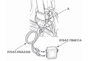
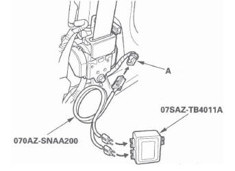
- SRS inflator simulator 07SAZ-TB4011A
- SRS simulator lead K 070AZ-SNAA200
NOTE: Before doing this troubleshooting procedure, review SRS Precautions and Procedures.
1. Erase the DTC memory.
2. Turn the ignition switch ON (II), and check that the SRS indicator comes on for about 6 seconds and then goes off.
Does the SRS indicator stay on, and is DTC 21-1x indicated? YES-Go to step 3.
NO-Intermittent failure, the system is OK at this time. Go to Troubleshooting Intermittent Failures. If another DTC is indicated, go to the DTC Troubleshooting Index.
3. Turn the ignition switch OFF. Disconnect the negative cable from the battery, and wait for 3 minutes.
4. Disconnect the floor wire harness 4P connector (A) from the driver's seat belt tensioner.
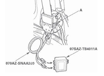
5. Connect the SRS inflator simulator (2 Ω connectors) and simulator lead K to the floor wire harness.
6. Reconnect the negative cable to the battery.
7. Erase the DTC memory.
8. Read the DTC.
Is DTC 21-1x indicated? YES-Go to step 9.
NO-Open or increased resistance in the driver's seat belt tensioner; replace the driver's seat belt.
9. Turn the ignition switch OFF. Disconnect the negative cable from the battery, and wait for 3 minutes.
10. Disconnect both seat belt buckle tensioner 4P connectors (see step 8) and the front passenger's seat belt tensioner 4P connector (see step 7 ).
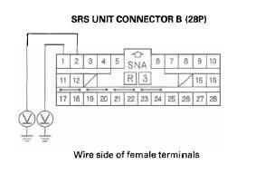
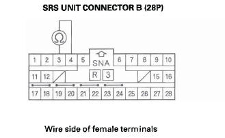
11. Disconnect SRS unit connector B (28P) from the SRS unit (see step 9).
12. Check resistance between the No.1 and the No.2 terminals of SRS unit connector B (28P). There should be 2.0-3.0 Ω.
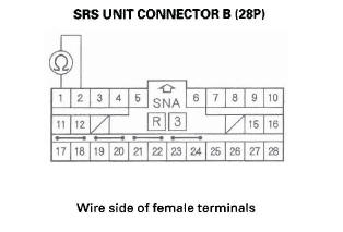
Is the resistance as specified? YES-Faulty SRS unit or poor connection at SRS unit connector B (28P) and the SRS unit. Check the connection; if the connection is OK, replace the SRS unit.
NO-Open or increased resistance in the floor wire harness; replace the floor wire harness.
DTC 21-3x ("X" can be 0 thru 9 or A thru F): Short to Another Wire or Decreased Resistance in Driver's Seat Belt Tensioner
Special Tools Required
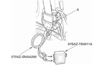
- SRS inflator simulator 07SAZ-TB4011A
- SRS simulator lead K 070AZ-SNAA200
NOTE: Before doing this troubleshooting procedure, review SRS Precautions and Procedures.
1. Erase the DTC memory.
2. Turn the ignition switch ON (II), and check that the SRS indicator comes on for about 6 seconds and then goes off.
Does the SRS indicator stay on, and is DTC 21-3x indicated? YES-Go to step 3.
NO-Intermittent failure, the system is OK at this time. Go to Troubleshooting Intermittent Failures. If another DTC is indicated, go to the DTC Troubleshooting Index.
3. Turn the ignition switch OFF. Disconnect the negative cable from the battery, and wait for 3 minutes.
4. Disconnect the floor wire harness 4P connector (A) from the driver's seat belt tensioner.
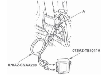
5. Connect the SRS inflator simulator (2 Ω connectors) and simulator lead K to the floor wire harness.
6. Reconnect the negative cable to the battery.
7. Erase the DTC memory.
8. Read the DTC.
Is DTC 21-3x1ndicated? YES-Go to step 9.
NO-Short in the driver's seat belt tensioner; replace the driver's seat belt.
9. Turn the ignition switch OFF. Disconnect the negative cable from the battery, and wait for 3 minutes.
10. Disconnect both seat belt buckle tensioner 4P connectors (see step 8) and the front passenger's seat belt tensioner 4P connector (see step 7).
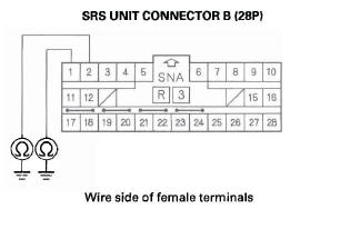
11. Disconnect SRS unit connector B (28P) from the SRS unit (see step 9).
12. Disconnect the simulator lead from the floor wire harness.
13. Check resistance between the No.1 and the No.2 terminals of SRS unit connector B (28P). There should be an open circuit (ohmmeter reads OL) or at least 1 M Ω.
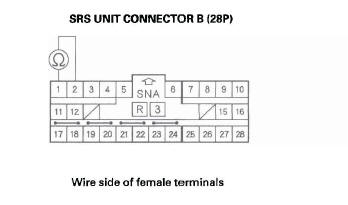
Is the resistance as specified? YES-Faulty SRS unit or poor connection at SRS unit connector B (28P) and the SRS unit. Check the connection; if the connection is OK, replace the SRS unit.
NO-Short in the floor wire harness; replace the floor wire harness.
DTC 21-8x ("x" can be 0 thru 9 or A thru F): Short to Power in Driver's Seat Belt Tensioner
Special Tools Required
- SRS inflator simulator 07SAZ-TB4011A
- SRS simulator lead K 070AZ-SNAA200
NOTE: Before doing this troubleshooting procedure, review SRS Precautions and Procedures.
1. Erase the DTC memory.
2. Turn the ignition switch ON (II), and check that the SRS indicator comes on for about 6 seconds and then goes off.
Does the SRS indicator stay on, and is DTC 21-8x indicated? YES-Go to step 3.
NO-Intermittent failure, the system is OK at this time. Go to Troubleshooting Intermittent Failures. If another DTC is indicated, go to the DTC Troubleshooting Index.
3. Turn the ignition switch OFF. Disconnect the negative cable from the battery, and wait for 3 minutes.
4. Disconnect the floor wire harness 4P connector (A) from the driver's seat belt tensioner.
5. Connect the SRS inflator simulator (2 Ω connectors) and simulator lead K to the floor wire harness.
6. Reconnect the negative cable to the battery.
7. Erase the DTC memory.
8. Read the DTC.
Is DTC 21-8x indicated? YES-Go to step 9.
NO-Short to power in the driver's seat belt tensioner; replace the driver's seat belt.
9. Turn the ignition switch OFF. Disconnect the negative cable from the battery, and wait for 3 minutes.
10. Disconnect both seat belt buckle tensioner 4P connectors (see step 8) and the front passenger's seat belt tensioner 4P connector (see step 7).
11. Disconnect SRS unit connector B (28P) from the SRS unit (see step 9).
12. Disconnect the simulator lead from the floor wire harness.
13. Reconnect the negative cable to the battery.
14. Turn the ignition switch ON (II).
15. Check for voltage between the No.1 terminal of SRS unit connector B (28P) and body ground, and between the No.2 terminal and body ground.
There should be 0.5 V or less.
Is the voltage as specified? YES-Faulty SRS unit or poor connection at SRS unit connector B (28P) and the SRS unit. Check the connection; if the connection is OK, replace the SRS unit.
NO-Short to power in the floor wire harness; replace the floor wire harness.
DTC 21-9x ("x" can be 0 thru 9 or A thru F): Short to Ground in Driver's Seat Belt Tensioner
Special Tools Required
- SRS inflator simulator 07SAZ-TB4011A
- SRS simulator lead K 070AZ-SNAA200
NOTE: Before doing this troubleshooting procedure, review SRS Precautions and Procedures.
1. Erase the DTC memory.
2. Turn the ignition switch ON (II), and check that the SRS indicator comes on for about 6 seconds and then goes off.
Does the SRS indicator stay on, and is DTC 21-9x indicated? YES-Go to step 3.
NO-Intermittent failure, the system is OK at this time. Go to Troubleshooting Intermittent Failures. If another DTC is indicated, go to the DTC Troubleshooting Index.
3. Turn the ignition switch OFF. Disconnect the negative cable from the battery, and wait for 3 minutes.
4. Disconnect the floor wire harness 4P connector (A) from the driver's seat belt tensioner.
5. Connect the SRS inflator simulator (2 Ω connectors) and simulator lead K to the floor wire harness.
6. Reconnect the negative cable to the battery.
7. Erase the DTC memory.
8. Read the DTC.
Is DTC 21-9x indicated? YES-Go to step 9.
NO-Short to ground in the driver's seat belt tensioner; replace the driver's seat belt.
9. Turn the ignition switch OFF. Disconnect the negative cable from the battery, and wait for 3 minutes.
10. Disconnect both seat belt buckle tensioner 4P connectors (see step 8) and the front passenger's seat belt tensioner 4P connector (see step 7).
11. Disconnect SRS unit connector B (28P) from the SRS unit (see step 9).
12. Disconnect the simulator lead from the floor wire harness.
13. Check resistance between the No.1 terminal of SRS unit connector B (28P) and body ground, and between the No.2 terminal and body ground.
There should be an open circuit (ohmmeter reads OL) or at least 1 M Ω.
Is the resistance as specified? YES-Faulty SRS unit or poor connection at SRS unit connector B (28P) and the SRS unit. Check the connection; if the connection is OK, replace the SRS unit.
NO-Short to ground in the floor wire harness; replace the floor wire harness.
DTC 22-1x ("x" can be 0 thru 9 or A thru F): Open or Increased Resistance in Front Passenger's Seat Belt Tensioner
Special Tools Required
- SRS inflator simulator 07SAZ-TB4011A
- SRS simulator lead K 070AZ-SNAA200
NOTE: Before doing this troubleshooting procedure, review SRS Precautions and Procedures.
1. Erase the DTC memory.
2. Turn the ignition switch ON (II), and check that the SRS indicator comes on for about 6 seconds and then goes off.
Does the SRS indicator stay on, and is DTC 22-1x indicated? YES-Go to step 3.
NO-Intermittent failure, the system is OK at this time. Go to Troubleshooting Intermittent Failures. If another DTC is indicated, go to the DTC Troubleshooting Index.
3. Turn the ignition switch OFF. Disconnect the negative cable from the battery, and wait for 3 minutes.
4. Disconnect the floor wire harness 4P connector (A) from the front passenger's seat belt tensioner.
6. Reconnect the negative cable to the battery.
7. Erase the DTC memory.
8. Read the DTC.
Is DTC 22-1x indicated? YES-Go to step 9.
NO-Open or increased resistance in the front passenger's seat belt tensioner; replace the front passenger's seat belt.
9. Turn the ignition switch OFF. Disconnect the negative cable from the battery, and wait for 3 minutes.
10. Disconnect both seat belt buckle tensioner 4P connectors (see step 8) and the driver's seat belt tensioner 4P connector (see step 7 on page 24-24).
11. Disconnect SRS unit connector B (28P) from the SRS unit (see step 9).
12. Check resistance between the No.3 and the No.4 terminals of SRS unit connector B (28P). There should be 2.0-3.0 Ω.
Is the resistance as specified? YES-Faulty SRS unit or poor connection at SRS unit connector B (28P) and the SRS unit. Check the connection; if the connection is OK, replace the SRS unit.
NO-Open or increased resistance in the floor wire harness; replace the floor wire harness.
READ NEXT:
 DTC 22-3x ("x" can be 0 thru 9 or A thru F):
Short to Another Wire or Decreased
Resistance in Front Passenger's Seat Belt
Tensioner
DTC 22-3x ("x" can be 0 thru 9 or A thru F):
Short to Another Wire or Decreased
Resistance in Front Passenger's Seat Belt
Tensioner
Special Tools Required
SRS inflator simulator 07SAZ-TB4011A
SRS simulator lead K 070AZ-SNAA200
NOTE: Before doing this troubleshooting procedure,
review SRS Precautions and Procedures.
1. Erase th
DTC 28-3x ("x" can be 0 thru 9 or A thru F):
Short to Another Wire or Decreased
Resistance in Front Passenger's Seat Belt
Buckle Tensioner
Special Tools Required
SRS inflator simulator 07SAZ-TB4011A
SRS simulator lead K 070AZ-SNAA200
NOTE: Before doing this troubleshooting procedure, review SRS Precautions and
Procedures.
1. Erase t
DTC 31-3x ("x" can be 0 thru 9 or A thru F):
Short to Another Wire or Decreased
Resistance in Driver's Side Airbag Inflator
Special Tools Required
SRS inflator simulator 07SAZ-TB4011A
SRS simulator lead L 070AZ-SNAA300
SRS short canceller 070AZ-SAA0100
NOTE: Before doing this troubleshooting procedure, review SRS Prec
SEE MORE:
Auto Door Locking
The auto door locking feature has
three possible settings:
The auto door locking is
deactivated all the time.
The doors and tailgate lock
whenever you move the shift lever
out of the Park (P) position.
The doors and tailgate lock when
the vehicle speed reaches 9 mph
(15 km/h).
This i
To Select a File from iPod Menu
You can also select a file from any
list on the iPod menu: playlists,
artists, albums and songs. Press the
AUDIO button to display the screen,
then touch the iPodMENU icon.
Select the desired mode by touching
the appropriate icon, or move the
joystick, then press ENT.
Press the AUD
