Honda CR-V: DTC 31-3x ("x" can be 0 thru 9 or A thru F): Short to Another Wire or Decreased Resistance in Driver's Side Airbag Inflator
Special Tools Required
- SRS inflator simulator 07SAZ-TB4011A
- SRS simulator lead L 070AZ-SNAA300
- SRS short canceller 070AZ-SAA0100
NOTE: Before doing this troubleshooting procedure, review SRS Precautions and Procedures.
1. Erase the DTC memory.
2. Turn the ignition switch ON (II), and check that the SRS indicator comes on for about 6 seconds and then goes off.
Does the SRS indicator stay on, and is DTC 31-3x indicated? YES-Go to step 3.
NO-Intermittent failure, the system is OK at this time. Go to Troubleshooting Intermittent Failures. If another DTC is indicated, go to the DTC Troubleshooting Index.
3. Turn the ignition switch OFF. Disconnect the negative cable from the battery, and wait for 3 minutes.
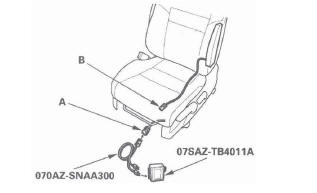
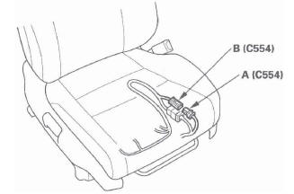
4. Disconnect the floor wire harness 2P connector (A) from the driver's side airbag (B).
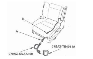
5. Connect the SRS inflator simulator (2 Ω connectors) and simulator lead L to the floor wire harness.
6. Reconnect the negative cable to the battery.
7. Erase the DTC memory.
8. Read the DTC.
Is DTC 31-3x indicated? YES-Go to step 9.
NO-Short to another wire in the driver's side airbag inflator; replace the driver's side airbag.
9. Turn the ignition switch OFF. Disconnect the negative cable from the battery, and wait for 3 minutes.
10. Disconnect both seat belt tensioner 4P connectors (see step 7) and both seat belt buckle tensioner 4P connectors (see step 8).
11. Disconnect SRS unit connector B (28P) from the SRS unit (see step 9).
12. Disconnect the SRS inflator simulator from the SRS simulator lead. Do not disconnect the simulator lead from the floor wire harness 2P connector.
13. Connect the SRS short canceller (070AZ-SAA0100) to the No. 17 and No. 18 terminals of SRS unit connector B (28P).
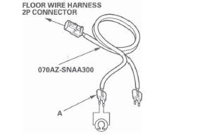
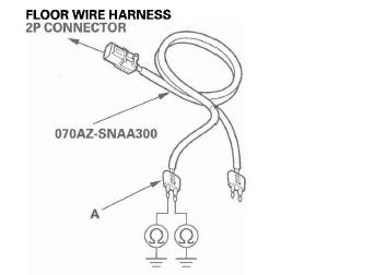
14. Check resistance between the terminals of the black SRS simulator lead (A). There should be an open circuit (ohmmeter reads OL) or at least 1 M Ω.
Is the resistance as specified? YES-Faulty SRS unit or poor connection at SRS unit connector B (28P) and the SRS unit. Check the connection; if the connection is OK, replace the SRS unit.
NO-Short in the floor wire harness; replace the floor wire harness.
DTC 31-8x ("X" can be 0 thru9 or A thru F): Short to Power in Driver's Side Airbag Inflator
Special Tools Required
- SRS inflator simulator 07SAZ-TB4011A
- SRS simulator lead L 070AZ-SNAA300
NOTE: Before doing this troubleshooting procedure, review SRS Precautions and Procedures.
1. Erase the DTC memory.
2. Turn the ignition switch ON (II), and check that the SRS indicator comes on for about 6 seconds and then goes off.
Does the SRS indicator stay on, and is DTC 31-8x indicated? YES-Go to step 3.
NO-Intermittent failure, the system is OK at this time. Go to Troubleshooting Intermittent Failures. If another DTC is indicated, go to the DTC Troubleshooting Index.
3. Turn the ignition switch OFF. Disconnect the negative cable from the battery, and wait for 3 minutes.
4. Disconnect the floor wire harness 2P connector (A) from the driver's side airbag (B).
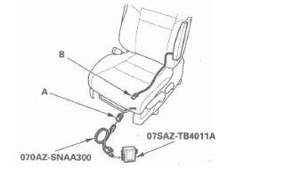
5. Connect the SRS inflator simulator (2 Ω connectors) and simulator lead L to the floor wire harness.
6. Reconnect the negative cable to the battery.
7. Erase the DTC memory.
8. Read the DTC.
Is DTC 31-8x indicated? YES-Go to step 9.
NO-Short to power in the driver's side airbag inflator; replace the driver's side airbag.
9. Turn the ignition switch OFF. Disconnect the negative cable from the battery, and wait for 3 minutes.
10. Disconnect both seat belt tensioner 4P connectors (see step 7) and both seat belt buckle tensioner 4P connectors (see step 8).
11. Disconnect SRS unit connector B (28P) from the SRS unit (see step 9).
12. Disconnect the SRS inflator simulator from the SRS simulator lead. Do not disconnect the simulator lead from the floor wire harness 2P connector.
13. Reconnect the negative cable to the battery.
14. Turn the ignition switch ON (II).
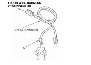
15. Check for voltage between each terminal of the black SRS simulator lead (A) and body ground.
There should be 0.5 V or less.
Is the voltage as specified? YES-Faulty SRS unit or poor connection at SRS unit connector B (28P) and the SRS unit. Check the connection; if the connection is OK, replace the SRS unit.
NO-Short to power in the floor wire harness; replace the floor wire harness.
DTC 31-9x ("x" can be 0 thru 9 or A thru F): Short to Ground in Driver's Side Airbag Inflator
Special Tools Required
- SRS inflator simulator 07SAZ-TB4011A
- SRS simulator lead L 070AZ-SNAA300
NOTE: Before doing this troubleshooting procedure, review SRS Precautions and Procedures.
1. Erase the DTC memory.
2. Turn the ignition switch ON (11), and check that the SRS indicator comes on for about 6 seconds and then goes off.
Does the SRS indicator stay on, and is DTC 31-9x indicated? YES-Go to step 3.
NO-Intermittent failure, the system is OK at this time. Go to Troubleshooting Intermittent Failures. If another DTC is indicated, go to the DTC Troubleshooting Index.
3. Turn the ignition switch OFF. Disconnect the negative cable from the battery, and wait for 3 minutes.
4. Disconnect the floor wire harness 2P connector (A) from the driver's side airbag (B).
5. Connect the SRS inflator simulator (2 Ω connectors) and simulator lead l to the floor wire harness.
6. Reconnect the negative cable to the battery.
7. Erase the DTC memory.
8. Read the DTC.
Is DTC 31-9x indicated? YES-Go to step 9.
NO-Short to ground in the driver's side airbag inflator; replace the driver's side airbag.
9. Turn the ignition switch OFF. Disconnect the negative cable from the battery, and wait for 3 minutes.
10. Disconnect both seat belt tensioner 4P connectors (see step 7) and both seat belt buckle tensioner 4P connectors (see step 8).
11. Disconnect SRS unit connector B (28P) from the SRS unit (see step 9).
12. Disconnect the SRS inflator simulator from the SRS simulator lead. Do not disconnect the simulator lead from the floor wire harness 2P connector.
13. Check resistance between each terminal of the black SRS simulator lead (A) and body ground.
There should be an open circuit (ohmmeter reads OL) or at least 1 M Ω.
Is the resistance as specified? YES-Faulty SRS unit or poor connection at SRS unit connector B (28P) and the SRS unit. Check the connection; if the connection is OK, replace the SRS unit.
NO-Short to ground in the floor wire harness; replace the floor wire harness.
DTC 32-1x ("X" can be 0 thru 9 or A thru F): Open or Increased Resistance in Front Passenger's Side Airbag Inflator
Special Tools Required
- SRS inflator simulator 07SAZ-TB4011A
- SRS simulator lead L 070AZ-SNAA300
NOTE: Before doing this troubleshooting procedure, review SRS Precautions and Procedures.
1. Erase the DTC memory.
2. Turn the ignition switch ON (II), and check that the SRS indicator comes on for about 6 seconds and then goes off.
Does the SRS indicator stay on, and is DTC 32-1x indicated? YES-Go to step 3.
NO-Intermittent failure, the system is OK at this time. Go to Troubleshooting Intermittent Failures. If another DTC is indicated, go to the DTC Troubleshooting Index.
3. Turn the ignition switch OFF. Disconnect the negative cable from the battery, and wait for 3 minutes.
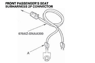
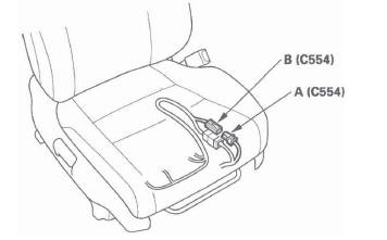
4. Disconnect the front passenger's seat subharness 2P connector (A) from the front passenger's side airbag (B).
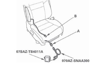
5. Connect the SRS inflator simulator (2 Ω connectors) and simulator lead L to the front passenger's seat subharness.
6. Reconnect the negative cable to the battery.
7. Erase the DTC memory.
8. Read the DTC.
Is DTC 32-1x indicated? YES-Go to step 9.
NO-Open or increased resistance in the front passenger's side airbag inflator; replace the front passenger's side airbag.
9. Turn the ignition switch OFF. Disconnect the negative cable from the battery, and wait for 3 minutes.
10. Disconnect both seat belt tensioner 4P connectors (see step 7) and both seat belt buckle tensioner 4P connectors (see step 8).
11. Disconnect SRS unit connector B (28P) from the SRS unit (see step 9).
12. Disconnect the SRS inflator simulator from the SRS simulator lead. Do not disconnect the simulator , lead from the front passenger's seat subharness 2P connector.
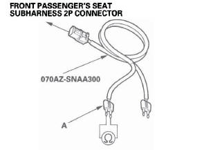
13. Check resistance between the terminals of the black SRS simulator lead (A). There should be 1.0 Ω or less.
Is the resistance as specified? YES-Faulty SRS unit or poor connection at SRS unit connector B (28P) and the SRS unit. Check the connection; if the connection is OK, replace the SRS unit.
NO-Go to step 14.
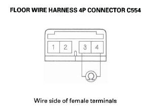
14. Disconnect floor wire harness 4P connector C554 (A) from front passenger's seat subharness 4P connector C554 (B).
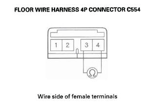
15. Check resistance between the No.3 and No.4 terminals of floor wire harness 4P connector C554.
There should be less than 1.0 Ω.
Is the resistance as specified? YES-Open or increased resistance in front passenger's seat subharness; replace the front passenger's seat subharness.
NO-Open or increased resistance in floor wire harness; replace the floor wire harness.
DTC 32-3x ("X" can be 0 thru 9 or A thru F): Short to Another Wire or Decreased Resistance in Front Passenger's Side Airbag Inflator
Special Tools Required
- SRS inflator simulator 07SAZ-TB4011A
- SRS simulator lead L 070AZ-SNAA300
- SRS short canceller 070AZ-SAA01 00
NOTE: Before doing this troubleshooting procedure, review SRS Precautions and Procedures.
1. Erase the DTC memory.
2. Turn the ignition switch ON (II), and check that the SRS indicator comes on for about 6 seconds and then goes off.
Does the SRS indicator stay on, and is DTC 32-3x indicated? YES-Go to step 3.
NO-Intermittent failure, the system is OK at this time. Go to Troubleshooting Intermittent Failures. If another DTC is indicated, go to the DTC Troubleshooting Index.
3. Turn the ignition switch OFF. Disconnect the negative cable from the battery, and wait for 3 minutes.
4. Disconnect the front passenger's seat subharness 2P connector (A) from the front passenger's side airbag (B).
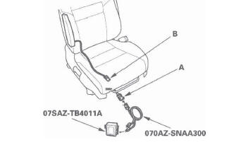
5. Connect the SRS inflator simulator (2 Ω connectors) and simulator lead L to the front passenger's seat subharness.
6. Reconnect the negative cable to the battery.
7. Erase the DTC memory.
8. Read the DTC.
Is DTC 32-3x indicated? YES-Go to step 9.
NO-Short to another wire in the front passenger's side airbag inflator; replace the front passenger's side airbag.
9. Turn the ignition switch OFF. Disconnect the negative cable from the battery, and wait for 3 minutes.
10. Disconnect both seat belt tensioner 4P connectors (see step 7) and both seat belt buckle tensioner 4P connectors (see step 8).
11. Disconnect SRS unit connector B (28P) from the SRS unit (see step 9).
12. Disconnect the SRS inflator simulator from the SRS simulator lead. Do not disconnect the simulator lead from the front passenger's seat subharness 2P connector.
13. Connect the SRS short canceller (070AZ-SAA0100) to the No. 19 and No. 20 terminals of SRS unit connector B (28P).
14. Check resistance between the terminals of the black SRS simulator lead (A). There should be an open circuit (ohmmeter reads OL) or at least 1 M Ω.
Is the resistance as specified? YES-Faulty SRS unit or poor connection at SRS unit connector B (28P) and the SRS unit. Check the connection; if the connection is OK, replace the SRS unit.
NO-Go to step 15.
15. Disconnect floor wire harness 4P connector C554 (A) from front passenger's seat subharness 4P connector C554 (B).
16. Check resistance between the No.3 and No.4 terminals of floor wire harness 4P connector C554.
There should be an open circuit (ohmmeter reads OL) or at least 1 M Ω.
Is the resistance as specified? YES-Short to another wire in front passenger's seat subharness; replace the front passenger's seat subharness.
NO-Short to another wire in floor wire harness; replace the floor wire harness.
READ NEXT:
 DTC 32-8x ("x" can be 0 thru 9 or A thru F):
Short to Power in Front Passenger's Side
Airbag Inflator
DTC 32-8x ("x" can be 0 thru 9 or A thru F):
Short to Power in Front Passenger's Side
Airbag Inflator
Special Tools Required
SRS inflator simulator 07SAZ-TB4011A
SRS simulator lead L 070AZ-SNAA300
NOTE: Before doing this troubleshooting procedure,
review SRS Precautions and Procedures.
1. Erase t
DTC 33-9x ("x" can be 0 thru 9 or A thru F):
Short to Ground in Left Side Curtain Airbag
Inflator
Special Tools Required
SRS inflator simulator 07SAZ-TB4011A
SRS simulator lead L 070AZ-SNAA300
NOTE: Before doing this troubleshooting procedure,
review SRS Precautions and Procedures.
1. Erase t
DTC 41-1x ("x" can be 0 thru 9 or A thru F):
No Signal From the Left Front Impact Sensor
Specia1 Tools Required
SRS inflator simulator 07SAZ-TB4011A
SRS simulator lead L 070AZ-SNAA300
NOTE: Before doing this troubleshooting procedure,
review SRS Precautions and Procedures.
1. Erase
SEE MORE:
Load Limits
The maximum load for your vehicle
is 850 lbs (385 kg) for U.S. vehicles,
and 395 kg for Canadian vehicles.
This figure includes the total weight
of all occupants, cargo, and
accessories, and the tongue load if
you are towing a trailer.
See Tire And Loading Information
label attached to
DTC 11, 13, 15, 17: Wheel Sensor (Open/Short
to Body Ground/Short to Power)
1. Turn the ignition switch ON (II).
2. Check for DTCs with the HDS.
Is DTC 87 indicated with DTC 11,13,15, and/or 17
at the same time?
YES-Go to step 9.
NO-Go to step 3.
3. Clear the DTC with the HDS.
4. Turn the ignition switch OFF, then turn it ON (II)
again.
5. Check for DTCs with the HDS.
