Honda CR-V: DTC 32-8x ("x" can be 0 thru 9 or A thru F): Short to Power in Front Passenger's Side Airbag Inflator
Special Tools Required
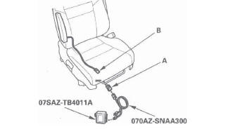
- SRS inflator simulator 07SAZ-TB4011A
- SRS simulator lead L 070AZ-SNAA300
NOTE: Before doing this troubleshooting procedure, review SRS Precautions and Procedures.
1. Erase the DTC memory.
2. Turn the ignition switch ON (II), and check that the SRS indicator comes on for about 6 seconds and then goes off.
Does the SRS indicator stay on, and is DTC 32-8x indicated? YES-Go to step 3.
NO-Intermittent failure, the system is OK at this time. Go to Troubleshooting Intermittent Failures. If another DTC is indicated, go to the DTC Troubleshooting Index.
3. Turn the ignition switch OFF. Disconnect the negative cable from the battery, and wait for 3 minutes.
4. Disconnect the front passenger's seat subharness 2P connector (A) from the front passenger's side airbag (B).
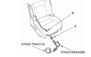
5. Connect the SRS inflator simulator (2 Ω connectors) and simulator lead L to the front passenger's seat subharness.
6. Reconnect the negative cable to the battery.
7. Erase the DTC memory.
8. Read the DTC.
Is DTC 32-8x indicated? YES-Go to step 9.
NO-Short to power in the front passenger's side airbag inflator; replace the front passenger's side airbag.
9. Turn the ignition switch OFF. Disconnect the negative cable from the battery, and wait for 3 minutes.
10. Disconnect both seat belt tensioner 4P connectors (see step 7) and both seat belt buckle tensioner 4P connectors (see step 8).
11. Disconnect SRS unit connector B (28P) from the SRS unit (see step 9).
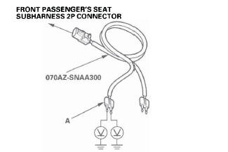
12. Disconnect the SRS inflator simulator from the SRS simulator lead. Do not disconnect the simulator lead from the front passenger's seat subharness 2P connector.
13. Reconnect the negative cable to the battery.
14. Turn the ignition switch ON (II).
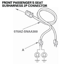
15. Check for voltage between each terminal of the black SRS simulator lead (A) and body ground.
There should be 0.5 V or less.
Is the voltage as specified? YES-Faulty SRS unit or poor connection at SRS unit connector B (28P) and the SRS unit. Check the connection; if the connection is OK, replace the SRS unit.
NO-Go to step 16.
16. Turn the ignition switch OFF.
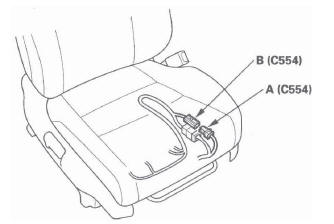
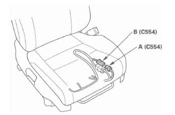
17. Disconnect floor wire harness 4P connector C554 (A) from front passenger's seat subharness 4P connector C554 (B).
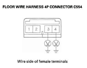
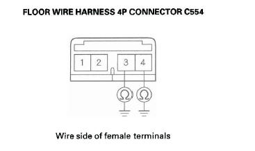
18. Check for voltage between the No.3 terminal of floor wire harness 4P connector C554 and body ground, and between the No.4 terminal and body ground. There should be less than 0.5 V.
Is the resistance as specified? YES-Short to power in front passenger's seat subharness; replace the front passenger's seat subharness.
NO-Short to power in floor wire harness; replace the floor wire harness.
DTC 32-9x ("x" can be 0 thru 9 or A thru F): Short to Ground in Front Passenger's Side Airbag Inflator
Special Tools Required
- SRS inflator simulator 07SAZ-TB4011A
- SRS simulator lead L 070AZ-SNAA300
NOTE: Before doing this troubleshooting procedure, review SRS Precautions and Procedures.
1. Erase the DTC memory.
2. Turn the ignition switch ON (II), and check that the SRS indicator comes on for about 6 seconds and then goes off.
Does the SRS indicator stay on, and is DTC 32-9x indicated? YES-Go to step 3.
NO-Intermittent failure, the system is OK at this time. Go to Troubleshooting Intermittent Failures. If another DTC is indicated, go to the DTC Troubleshooting Index.
3. Turn the ignition switch OFF. Disconnect the negative cable from the battery, and wait for 3 minutes.
4. Disconnect the front passenger's seat subharness 2P connector (A) from the front passenger's side airbag (B).
5. Connect the SRS inflator simulator (2 Ω connectors) and simulator lead L to the front passenger's seat subharness.
6. Reconnect the negative cable to the battery.
7. Erase the DTC memory.
8. Read the DTC.
Is DTC 32-9x indicated? YES-Go to step 9.
NO-Short to ground in the front passenger's side airbag inflator; replace the front passenger's side airbag.
9. Turn the ignition switch OFF. Disconnect the negative cable from the battery, and wait for 3 minutes.
10. Disconnect both seat belt tensioner 4P connectors (see step 7) and both seat belt buckle tensioner 4P connectors (see step 8).
11. Disconnect SRS unit connector B (28P) from the SRS unit (see step 9).
12. Disconnect the SRS inflator simulator from the SRS simulator lead. Do not disconnect the simulator lead from the front passenger's seat subharness 2P connector.
13. Check resistance between each terminal of the black SRS simulator lead (A) and body ground.
There should be an open circuit (ohmmeter reads OL) or at least 1 M Ω.
Is the resistance as specified? YES-Faulty SRS unit or poor connection at SRS unit connector B (28P) and the SRS unit. Check the connection; if the connection is OK, replace the SRS unit.
NO-Go to step 14.
14. Disconnect floor wire harness 4P connector C554 (A) from front passenger's seat subharness 4P connector C554 (B).
15. Check resistance between the No.3 terminal of floor wire harness 4P connector C554 and body ground, and between the No.4 terminal and body ground. There should be an open circuit (ohmmeter reads OL) or at least 1 M Ω.
Is the resistance as specified? YES-Short to ground in front passenger's seat subharness; replace the front passenger's seat subharness.
NO-Short to ground in floor wire harness; replace the floor wire harness.
DTC 33-1x ("X" can be 0 thru 9 or A thru F): Open or Increased Resistance in Left Side Curtain Airbag Inflator
Special Tools Required
- SRS inflator simulator 07SAZ-TB4011A
- SRS simulator lead L 070AZ-SNAA300
NOTE: Before doing this troubleshooting procedure, review SRS Precautions and Procedures.
1. Erase the DTC memory.
2. Turn the ignition switch ON (II), and check that the SRS indicator comes on for about 6 seconds and then goes off.
Does the SRS indicator stay on, and is DTC 33-1x indicated? YES-Go to step 3.
NO-Intermittent failure, the system is OK at this time. Go to Troubleshooting Intermittent Failures. If another DTC is indicated, go to the DTC Troubleshooting Index.
3. Turn the ignition switch OFF. Disconnect the negative cable from the battery, and wait for 3 minutes.
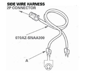
4. Remove the left side quarter pillar glass trim, then disconnect the side wire harness 2P connector (A) from the left side curtain airbag connector (B).
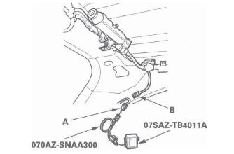
5. Connect the SRS inflator simulator (2 Ω connectors) and simulator lead L to the side wire harness.
6. Reconnect the negative cable to the battery.
7. Erase the DTC memory.
8. Read the DTC.
Is DTC 33-1x indicated? YES-Go to step 9.
NO-Open or increased resistance in the left side curtain airbag; replace the left side curtain airbag.
9. Turn the ignition switch OFF. Disconnect the negative cable from the battery, and wait for 3 minutes.
10. Disconnect both seat belt tensioner 4P connectors (see step 7) and both seat belt buckle tensioner 4P connectors (see step 8).
11. Disconnect SRS unit connector B (28P) from the SRS unit (see step 9).
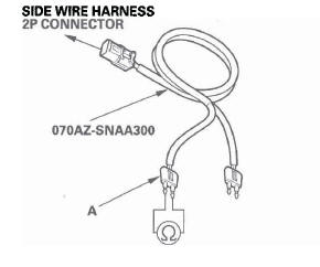
12. Disconnect the SRS inflator simulator from the SRS simulator lead. Do not disconnect the simulator lead from the side wire harness 2P connector.
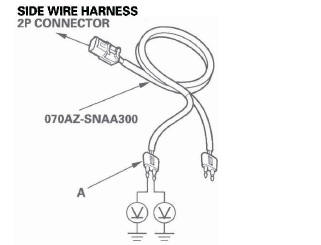
13. Check resistance between the terminals of the black SRS simulator lead (A). There should be 1.0 Ω or less.
Is the resistance as specified? YES-Faulty SRS unit or poor connection at the SRS unit connector B (28P) and the SRS unit. Check the connection; if the connection is OK, replace the SRS unit.
NO-Go to step 14.
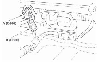
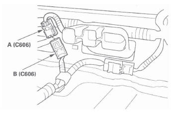
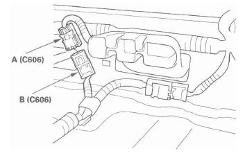
14. Disconnect floor wire harness 4P connector C606 (A) from side wire harness 4P connector C606 (B).
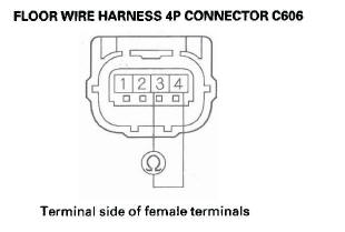
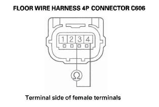
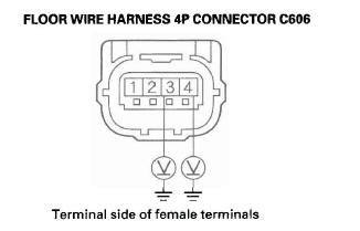
15. Check resistance between the. No.3 and No.4 terminals of floor wire harness 4P connector C606 (A). There should be less than 1.0 Ω.
Is the resistance as specified? YES-Open or increased resistance in the side wire harness; replace the side wire harness.
NO-Open or increased resistance in the floor wire harness; replace the floor wire harness.
DTC 33-3x ("x" can be 0 thru 9 or A thru F): Short to Another Wire or Decreased Resistance in Left Side Curtain Airbag Inflator
Special Tools Required
- SRS inflator simulator 07SAZ-TB4011A
- SRS simulator lead L 070AZ-SNAA300
- SRS short canceller 070AZ-SAA0100
NOTE: Before doing this troubleshooting procedure, review SRS Precautions and Procedures.
1. Erase the DTC memory.
2. Turn the ignition switch ON (II), and check that the SRS indicator comes on for about 6 seconds and then goes off.
Does the SRS indicator stay on, and is DTC 33-3x indicated? YES-Go to step 3.
NO-Intermittent failure, the system is OK at this time. Go to Troubleshooting Intermittent Failures. If another DTC is indicated, go to the DTC Troubleshooting Index.
3. Turn the ignition switch OFF. Disconnect the negative cable from the battery, and wait for 3 minutes.
4. Remove the left side quarter pillar glass trim, then disconnect the side wire harness 2P connector (A) from the left side curtain airbag connector (B).
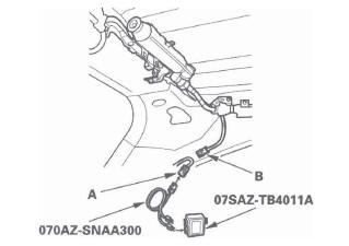
5. Connect the SRS inflator simulator (2 Ω connectors) and simulator lead L to the side wire harness.
6. Reconnect the negative cable to the battery.
7. Erase the DTC memory.
8. Read the DTC.
Is DTC 33-3x indicated? YES-Go to step 9.
NO-Short to another wire in the left side curtain airbag inflator; replace the left side curtain airbag.
9. Turn the ignition switch OFF. Disconnect the negative cable from the battery, and wait for 3 minutes.
10. Disconnect both seat belt tensioner 4P connectors (see step 7) and both seat belt buckle tensioner 4P connectors (see step 8).
11. Disconnect SRS unit connector B (28P) from the SRS unit (see step 9).
12. Disconnect the SRS inflator simulator from the SRS simulator lead. Do not disconnect the simulator lead from the side wire harness 2P connector.
13. Connect the SRS short canceller (070AZ-SAA0100) to the No. 21 and No. 22 terminals of SRS unit connector B (28P).
14. Check resistance between the terminals of the black SRS simulator lead (A). There should be an open circuit (ohmmeter reads OL) or at least 1 M Ω.
Is the resistance as specified? YES-Faulty SRS unit or poor connection at SRS unit connector B (28P) and the SRS unit. Check the connection; if the connection is OK, replace the SRS unit.
NO-Go to step 15.
15. Disconnect floor wire harness 4P connector C606 (A) from side wire harness 4P connector C606 (B).
16. Check resistance between the No.3 and No.4 terminals of floor wire harness 4P connector C606 (A). There should be an open circuit (ohmmeter reads OL) or at least 1 M Ω.
Is the resistance as specified? YES-Short to another wire in the side wire harness; replace the side wire harness.
NO-Short to another wire in the floor wire harness; replace the floor wire harness.
DTC 33-8x ("x" can be 0 thru 9 or A thru F): Short to Power in Left Side Curtain Airbag Inflator
Special Tools Required
- SRS inflator simulator 07SAZ-TB4011A
- SRS simulator lead L 070AZ-SNAA300
NOTE: Before doing this troubleshooting procedure, review SRS Precautions and Procedures.
1. Erase the DTC memory.
2. Turn the ignition switch ON (II), and check that the SRS indicator comes on for about 6 seconds and then goes off.
Does the SRS indicator stay on, and is DTC 33-8x indicated? YES-Go to step 3.
NO-Intermittent failure, the system is OK at this time. Go to Troubleshooting Intermittent Failures. If another DTC is indicated, go to the DTC Troubleshooting Index.
3. Turn the ignition switch OFF. Disconnect the negative cable from the battery, and wait for 3 minutes.
4. Remove the left side quarter pillar glass trim, then disconnect the side wire harness 2P connector (A) from the left side curtain airbag connector (B).
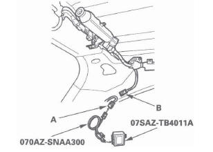
5. Connect the SRS inflator simulator (2 Ω connectors) and simulator lead L to the side wire harness.
6. Reconnect the negative cable to the battery.
7. Erase the DTC memory.
8. Read the DTC.
Is DTC 33-8x indicated? YES-Go to step 9.
NO-Short to power in the left side curtain airbag inflator; replace the left side curtain airbag.
9. Turn the ignition switch OFF. Disconnect the negative cable from the battery, and wait for 3 minutes.
10. Disconnect both seat belt tensioner 4P connectors (see step 7) and both seat belt buckle tensioner 4P connectors (see step 8).
11. Disconnect the SRS unit connector B (28P) from the SRS unit (see step 9).
12. Disconnect the SRS inflator simulator from the SRS simulator lead. Do not disconnect the simulator lead from the side wire harness 2P connector.
13. Reconnect the negative cable to the battery.
14. Turn the ignition switch ON (II).
15. Check for voltage between each terminal of the black SRS simulator lead (A) and body ground.
There should be 0.5 V or less.
Is the voltage as specified? YES-Faulty SRS unit or poor connection at SRS unit connector B (28P) and the SRS unit. Check the connection; if the connection is OK, replace the SRS unit.
NO-Go to step 16.
16. Turn the ignition switch OFF.
17. Disconnect floor wire harness 4P connector C606 (A) from side wire harness 4P connector C606 (B).
18. Check for voltage between the No.3 terminal of floor wire harness 4P connector C606 (A) and body ground, and between the No.4 terminal and body ground. There should be less than 0.5 V.
Is the voltage as specified? YES-Short to power in the side wire harness; replace the side wire harness.
NO-Short to power in the floor wire harness; replace the floor wire harness.
READ NEXT:
 DTC 33-9x ("x" can be 0 thru 9 or A thru F):
Short to Ground in Left Side Curtain Airbag
Inflator
DTC 33-9x ("x" can be 0 thru 9 or A thru F):
Short to Ground in Left Side Curtain Airbag
Inflator
Special Tools Required
SRS inflator simulator 07SAZ-TB4011A
SRS simulator lead L 070AZ-SNAA300
NOTE: Before doing this troubleshooting procedure,
review SRS Precautions and Procedures.
1. Erase t
DTC 41-1x ("x" can be 0 thru 9 or A thru F):
No Signal From the Left Front Impact Sensor
Specia1 Tools Required
SRS inflator simulator 07SAZ-TB4011A
SRS simulator lead L 070AZ-SNAA300
NOTE: Before doing this troubleshooting procedure,
review SRS Precautions and Procedures.
1. Erase
DTC 45-1x ("x" can be 0 thru 9 or A thru F):
No Signal From the Left Side Impact Sensor
(second)
Special Tools Required
SRS inflator simulator 07SAZ-TB4011A
SRS simulator lead L 070AZ-SNAA300
NOTE: Before doing this troubleshooting procedure, review SRS Precautions and
Procedures.
1. Erase t
SEE MORE:
Column Cover Removal/Installation
SRS components are located in this area. Review the
SRS component locations and the
precautions and procedures before
doing repairs or service.
NOTE: Take care not to scratch the dashboard and
related parts.
1. Release the tilt/telescopic lock lever, tilt the
steering wheel to fully down, and pull
Rear Brake
Rear Brake Pad Inspection and Replacement
Special Tools Required
Brake caliper piston compressor 07AAE-SEPA101
CAUTION
Frequent inhalation of brake pad dust, regardless of material
composition, could be hazardous to -your health.
Avoid breathing dust particles.
Never use an air hose or brush to
