Honda CR-V: DTC 45-1x ("x" can be 0 thru 9 or A thru F): No Signal From the Left Side Impact Sensor (second)
Special Tools Required
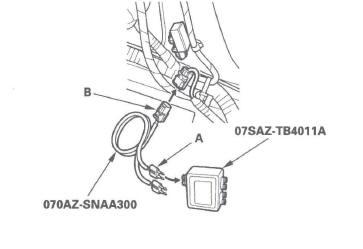
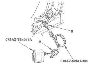
- SRS inflator simulator 07SAZ-TB4011A
- SRS simulator lead L 070AZ-SNAA300
NOTE: Before doing this troubleshooting procedure, review SRS Precautions and Procedures.
1. Erase the DTC memory.
2. Turn the ignition switch ON (II), and wait for 10 seconds.
3. Read the DTC.
Is DTC 45-11 indicated? YES-Go to step 4.
NO-Intermittent failure, system is OK at this time.
Go to Troubleshooting Intermittent Failures. If another DTC is indicated, go to the DTC Troubleshooting Index.
4. Read the DTC.
Is DTC 43-11 also indicated? YES-Faulty left side impact sensor (second); replace the left side impact sensor (second).
NO-Go to step 5.
5. Turn the ignition switch OFF.
6. Disconnect the negative cable from the battery, and wait for 3 minutes.
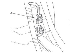
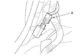
7. Disconnect side wire harness 2P connector (A) from the left side impact sensor (second).
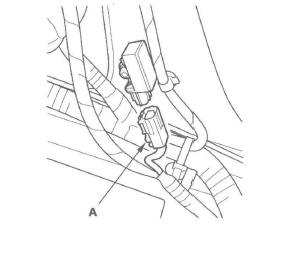
8. Disconnect the floor wire harness 4P connector (A) from the left side impact sensor (first).
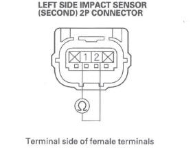
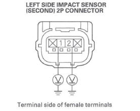
9. Check resistance between the No.1 and No.2 terminals of left side impact sensor (second) 2P connector. There should be an open circuit (ohmmeter reads OL) or at least 1 M Ω.
Is the resistance as specified? YES-Go to step 10.
NO-Short in the side wire harness or floor wire harness; replace the faulty harness.
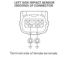
10. Check resistance between the No.1 terminal of left side impact sensor (second) 2P connector and body ground, and between the No.2 terminal and body ground. There should be an open circuit (ohmmeter reads OL) or at least 1 M Ω.
Is the resistance as specified? YES-Go to step 11.
NO-Short to ground in the side wire harness or floor wire harness; replace the faulty harness.
11. Reconnect the negative cable to the battery.
12. Turn the ignition switch ON (II).
13. Check for voltage between the No.1 terminal of left side impact sensor (second) 2P connector and body ground, and between the No.2 terminal and body ground. There should be 1 V or less.
Is the voltage as specified? YES-Go to step 14.
NO-Short to power in the side wire harness or floor wire harness; replace the faulty harness.
14. Turn the ignition switch OFF.
15. Connect the SRS inflator simulator (jumper connector) and the red lead (A) of simulator lead L to the left side impact sensor (first) 4P connector (B).
16. Check resistance between the No.1 and No.2 terminals of left side impact sensor (second) 2P connector. There should be 0-1.0 Ω.
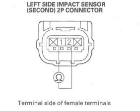
Is the resistance as specified? YES-Faulty left side impact sensor (second) or poor connection at left side impact sensor (second) 2P connector. Check the connection; If the connection is OK, replace the left side impact sensor (second).
NO-Open in the side wire harness or floor wire harness; replace the faulty harness.
DTC 46-1x ("X" can be 0 thru 9 or A thru F): No Signal From the Right Side Impact Sensor (second)
Special Tools Required
- SRS inflator simulator 07SAZ-TB4011A
- SRS simulator lead L 070AZ-SNAA300
NOTE: Before doing this troubleshooting procedure, review SRS Precautions and Procedures.
1. Erase the DTC memory.
2. Turn the ignition switch ON (II), and wait for 10 seconds.
3. Read the DTC.
Is DTC 46-11 indicated? YES-Go to step 5.
NO-Go to step 4.
4. Read the DTC.
Is DTC 46-12 also indicated? YES-Faulty right side impact sensor (second); replace the right side impact sensor (second).
NO-Intermittent failure, system is OK at this time.
Go to Troubleshooting Intermittent Failures. If another DTC is indicated, go to the DTC Troubleshooting Index.
5. Turn the ignition switch OFF.
6. Disconnect the negative cable from the battery, and wait for 3 minutes.
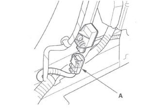
7. Disconnect the side wire harness 2P connector (A) from the right side impact sensor (second).
8. Disconnect the floor wire harness 4P connector (A) from the right side impact sensor (first).
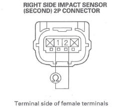
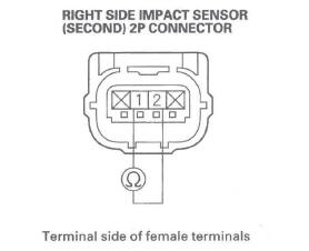
9. Check resistance between the No.1 and No.2 terminals of right side impact sensor (second) 2P connector. There should be an open circuit (ohmmeter reads OL) or at least 1 M Ω.
Is the resistance as specified? YES-Go to step 10.
NO-Short in the side wire harness or floor wire harness; replace the faulty harness.
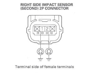
10. Check resistance between the No.1 terminal of right side impact sensor (second) 2P connector and body ground, and between the No.2 terminal and body ground. There should be an open circuit or at least 1 M Ω.
Is the resistance as specified? YES-Go to step 11.
NO-Short to ground in the side wire harness or floor wire harness; replace the faulty harness.
11. Reconnect the negative cable to the battery.
12. Turn the ignition switch ON (II).
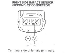
13. Check for voltage between the No.1 terminal of right side impact sensor (second) 2P connector and body ground, and between the No.2 terminal and body ground. There should be 1 V or less.
Is the voltage as specified? YES-Go to step 14.
NO-Short to power in the side wire harness or floor wire harness; replace the faulty harness.
14. Turn the ignition switch OFF.
15. Connect the SRS inflator simulator (jumper connector) and the red lead (A) of simulator lead L to the right side impact sensor (first) 4P connector (B).
16. Check resistance between the No.1 and No.2 terminals of right side impact sensor (second) 2P connector. There should be 0-1.0 Ω.
Is the resistance as specified? YES-Faulty right side impact sensor (second) or poor connection at right side impact sensor (second) 2P connector. Check the connection; If the connection is OK, replace the right side impact sensor (second).
NO-Open in the side wire harness or floor wire harness; replace the faulty harness.
DTC 45-2x, 45-8x, 45-Bx ("x" can be 0 thru 9 or A thru F): Internal Failure of the Left Side Impact Sensor (second)
DTC 46-2x, 46-8x, 46-Bx ("x" can be 0 thru 9 or A thru F): Internal Failure of Right Side Impact Sensor (second)
NOTE: Before doing this troubleshooting procedure, review SRS Precautions and Procedures.
1. Erase the DTC memory.
2. Turn the ignition switch ON (II), and check that the SRS indicator comes on for about 6 seconds and then goes off.
Does the SRS indicator stay on, and is DTC 45-2x, 45-8x, 45-Bx, 46-2x, 46-8x, or 46-Bx indicated? YES-Replace the left or right side impact sensor (second) (see page 24-178). If the DTC returns, replace the SRS unit.
NO-Intermittent failure, system is OK at this time.
Go to Troubleshooting Intermittent Failures (see page 24-27). If another DTC is indicated, go to the DTC Troubleshooting Index.
DTC 51-xx, 52:xx, 53-xx, 54-xx, 55-xx, 57-xx, 58-xx ("x" can be 0 thru 9 or A thru F): Internal Failure of the SRS Unit
NOTE:
- Before troubleshooting any of these DTCs, check the
battery/system voltage and battery cable connections.
If the voltage is low, repair the charging system or replace the battery before troubleshooting the SRS. If the battery/system voltage is now OK, ask the customer if the battery ever went dead or if the engine was started and run with the battery in a low state of change. A dead battery may trigger one or more of these DTCs.
- Before doing this troubleshooting procedure, review SRS Precautions and Procedures.
1. Erase the DTC memory.
2. Turn the ignition switch ON (II), and check that the SRS indicator comes on for about 6 seconds and then goes off.
Does the SRS indicator stay on, and is DTC 51-xx, 52-xx, 53-xx, 54-xx, 55-xx, 57-xx, or 58-xx indicated? YES-Replace the SRS unit.
NO-Intermittent failure, the system is OK at this time. Go to Troubleshooting Intermittent Failures. If another DTC is indicated, go to the DTC Troubleshooting Index.
DTC E2-11, E4-11, F1-11, F2-11, F3-11, F4-11: Airbags, Side Airbags, Side Curtain Airbags, Seat Belt Tensioners and/or Seat Belt Buckle Tensioners Deployed
The SRS unit must be replaced after any airbags and/or tensioners have deployed.
NOTE:
- DTC E2-11 is set if the system triggered airbag deployment but the front passenger's airbag was prevented from deploying because of the seat weight sensor.
- DTC E4-11 is set if the system triggered a passenger's side airbag deployment but the airbag was prevented from deploying by the ODS. Replace the right side impact sensor (first).
- Before doing this troubleshooting procedure, review SRS Precautions and Procedures.
DTC 56-11: Lost Communication with the PCM (engine message)
DTC 56-21: Lost Communication with the PCM (A/T message)
NOTE:
- Before doing this troubleshooting procedure, review SRS Precautions and Procedures.
- Check for any F-CAN and B-CAN communication DTCs, and troubleshoot those DTCs before doing this troubleshooting procedure.
1. Turn the ignition switch ON (II), and see if the malfunction indicator lamp (MIL) or D indicator come on.
Does the MIL or 0 indicator come on? YES-Go to step 2.
NO-Go to the PGM-FI System MIL circuit troubleshooting or A/T system General Troubleshooting Information.
2. Erase the DTC memory.
3. Turn the ignition switch ON (II), and wait for 10 seconds.
4. Read the DTC.
Is DTC 56-11 or 56-21 indicated? YES-Go to step 5.
NO-Intermittent failure, the system is OK at this time. Go to Troubleshooting Intermittent Failures. If another DTC is indicated, go to the DTC Troubleshooting Index.
5. Turn the ignition switch OFF.
6. Disconnect the negative cable from the battery, and wait for 3 minutes.
7. Disconnect SRS unit connector A (28P) from the SRS unit (see step 9).
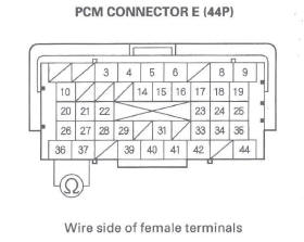
8. Disconnect PCM connector E (44P) from the PCM.
9. Install a jumper wire between the No. 11 and No. 12 terminals of SRS unit connector A (28P).
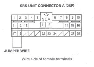
10. Check resistance between the No. 36 and No. 37 terminals of PCM connector E (44P). There should be 0-1.0 Ω.
Is the r,esistance as specified? YES-Faulty SRS unit or poor connection at SRS unit connector A (28P) and the SRS unit. Check the connection between the connector and the SRS unit. If the connection is OK, replace the SRS unit.
NO-Open between the No. 11 terminal of SRS unit connector A (28P) and No. 36 terminal of PCM connector E (44P), or between the No. 12 terminal of SRS unit connector A (28P) and No. 37 terminal of PCM connector E (44P); replace the faulty harness.
DTC 56-12, 56-13: Undefined Data Received From the PCM (engine message)
DTC 56-22, 56-23: Undefined Data Received From the PCM (A/T message)
NOTE:
- Before doing this troubleshooting procedure, review SRS Precautions and Procedures.
- Check for any F-CAN and B-CAN communication DTCs, and troubleshoot those DTCs before doing this troubleshooting procedure.
1. Turn the ignition switch ON (II), and see if the malfunction indicator lamp (MIL) or D indicator come on.
Does the MIL or D indicator come on? YES-Go to step 2.
NO-Go to the PGM-FI System MIL circuit troubleshooting or A/T system General Troubleshooting Information.
2. Erase the DTC memory.
3. Turn the ignition switch ON (II), and wait for 10 seconds.
4. Read the DTC (.
Is DTC 56-12, 56-13, 56-22 or 56-23 indicated? YES-Faulty PCM; replace the PCM.
NO-Intermittent failure, the system is OK at this time. Go to Troubleshooting Intermittent Failures. If another DTC is indicated, go to the DTC Troubleshooting Index.
DTC 56-25: Lost communication with the Gauge Control Module
NOTE:
- Before doing this troubleshooting procedure, review SRS Precautions and Procedures.
- Check for any F-CAN and B-CAN communication DTCs, and troubleshoot those DTCs before doing this troubleshooting procedure.
1. Release the parking brake, turn the ignition switch ON (II), and see if the brake system light comes on for 2 seconds and then goes off.
Does the brake system light come on? YES-Go to step 2.
NO-Faulty gauge control module. Do the gauge control module self-diagnostic function.
2. Erase the DTC memory.
3. Turn the ignition switch ON (II), and wait for 10 seconds.
4. Read the DTC.
Is DTC 56-25 indicated? YES-Go to step 5.
NO-Intermittent failure, the system is OK at this time. Go to Troubleshooting Intermittent Failures. If another DTC is indicated, go to the DTC Troubleshooting Index.
5. Turn the ignition switch OFF.
6. Disconnect the negative cable from the battery, and wait for 3 minutes.
7. Disconnect SRS unit connector A (28P) from the SRS unit (see step 9).
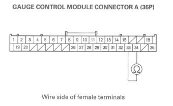
8. Disconnect gauge control module connector A (36P) from the gauge control module.
9. Install a jumper wire between the No. 11 and No. 12 terminals of SRS unit connector A (28P).
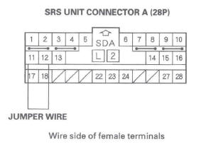
10. Check resistance between the No. 33 and No. 34 terminals of gauge control module connector A (36P). There should be 0-1.0 Ω.
Is the resistance as specified? YES-Faulty SRS unit or poor connection at SRS unit connector A (28P) and the SRS unit. Check the connection between the connector and the SRS unit. If the connection is OK, replace the SRS unit.
NO-Open between the No. 11 terminal of SRS unit connector A (28P) and No. 34 terminal of gauge control module connector A (36P), and between the No. 12 terminal of SRS unit connector A (28P) and No. 33 terminal of gauge control module connector A (36P); replace the faulty harness.
DTC 56-26, 56-27: Undefined Data Received From the Gauge Control Module
NOTE:
- Before doing this troubleshooting procedure, review SRS Precautions and Procedures.
- Check for any F-CAN and B-CAN communication DTCs, and troubleshoot those DTCs before doing this troubleshooting procedure.
1. Erase the DTC memory.
2. Turn the ignition switch ON (II), and wait for 10 seconds.
3. Read the DTC.
Is DTC 56-26 or 56-27 indicated? YES-Faulty gauge control module; replace the gauge control module.
NO-Intermittent failure, the system is OK at this time. Go to Troubleshooting Intermittent Failures. If another DTC is indicated, go to the DTC Troubleshooting Index.
DTC 61-1x ("X" can be 0 thru 9 or A thru F): Open in the Driver's Seat Belt Buckle Switch
NOTE: Before doing this troubleshooting procedure, review SRS Precautions and Procedures /
1. Erase the DTC memory.
2. Turn the ignition switch ON (II), then buckle and unbuckle the driver's seat belt several times.
3. Read the DTC.
Is DTC 61-1x indicated? YES-Go to step 4.
NO-Intermittent failure, the system is OK at this time. Go to Troubleshooting Intermittent Failures. If another DTC is indicated, go to the DTC troubleshooting Index.
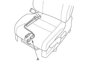
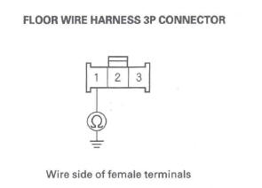
4. Disconnect the floor wire harness 3P connector from the driver's seat belt buckle switch 3P connector (A).
5. From the system selection menu on the HDS, select SRS, then select SRS again, then select PARAMETER INFORMATION, then Buckles Switch.
Seat Position Sensor, and check the status on the HDS screen for FRONT LEFT SEAT BELT BUCKLE SWITCH when the seat belt is buckled, and unbuckled.
- If UNBUCKLE, BUCKLE, or SHORT is indicated replace the floor wire harness.
- If OPEN is indicated, go to step 6.
6. Check resistance between the No.1 terminal of the floor wire harness 3P connector and body ground.
There should be 0-1 Ω.
Is the resistance as specified? YES-Go to step 7.
NO-Open in the floor wire harness or poor ground connection at G551.
7. Alternately connect the No.2 and No.3 terminals of the floor wire harness 3P connector to body ground with a jumper wire, and check the status on the HDS screen.
Does the status alternate from UNBUCKLE to BUCKLE? YES-Replace the driver's seat belt buckle assembly (see page 24-6), then clear the DTC.
NO-Open in the floor wire harness; replace the floor wire harness.
DTC 61-2x ("X" can be 0 thru 9 or A thru F): Short in Driver's Seat Belt Buckle Switch
NOTE: Before doing this troubleshooting procedure, review SRS Precautions and Procedures.
1. Erase the DTC memory.
2. Turn the ignition switch ON (II), then buckle and unbuckle the driver's seat belt several times.
3. Read the DTC.
Is DTC 61-2x indicated? YES-Go to step 4.
NO-Intermittent failure, the system is OK at this time. Go to Troubleshooting Intermittent Failures. If another DTC is indicated, go to the DTC Troubleshooting Index.
4. Turn the ignition switch OFF.
5. Disconnect the floor wire harness 3P connector from the driver's seat belt buckle switch 3P connector (A).
6. Turn the ignition switch ON (II).
7. From the system selection menu on the HDS, select SRS, then select SRS again, then select PARAMETER INFORMATION, then Buckle Switch, Seat Position Sensor, and check the status on the HDS screen for FRONT LEFT SEAT BELT BUCKLE SWITCH.
Is OPEN indicated on the HDS? YES-Replace the driver's seat belt buckle assembly, then clear the DTC.
NO-Short to ground in the floor wire harness; replace the floor wire harness.
DTC 62-1x ("x" can be 0 thru 9 or A thru F): Open in the Front Passenger's Seat Belt Buckle Switch
NOTE: Before doing this troubleshooting procedure, review SRS Precautions and Procedures.
1. Erase the DTC memory.
2. Turn the ignition switch ON (11), then buckle and unbuckle the driver's seat belt several times.
3. Read the DTC.
Is DTC 62-1x indicated? YES-Go to step 4.
NO-Intermittent failure, the system is OK at this time. Go to Troubleshooting Intermittent Failures. If another DTC is indicated, go to the DTC Troubleshooting Index.
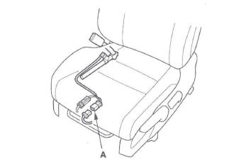
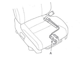
4. Disconnect the front passenger's seat subharness 3P connector from the front passenger's seat belt buckle switch 3P connector (A).
5. From the system selection menu on the HDS, select SRS, then select SRS again, then select PARAMETER INFORMATION, then Buckle Switch.
Seat Position Sensor, and check the status on the HDS screen for FRONT RIGHT SEAT BELT BUCKLE SWITCH when the seat belt is buckled, and unbuckled.
- If UNBUCKLE, BUCKLE, or SHORT is indicated open in the front passenger's seat subharness, or floor wire harness; replace the faulty harness.
- If OPEN is indicated, go to step 6.
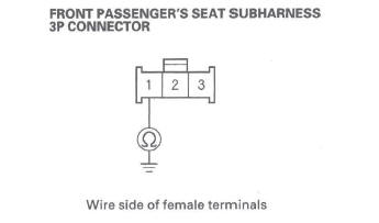
6. Check resistance between the No.1 terminal of the front passenger's seat subharness 3P connector and body ground. There should be 0-1 Ω.
Is the resistance as specified? YES-Go to step 7.
NO-Open in the front passenger's seat subharness, or floor wire harness or poor ground connection at G552. If G552 is OK, replace the faulty harness.
7. Alternately connect the No.2 and No.3 terminals of the front passenger's seat subharness 3P connector to body ground with a jumper wire, and check the status on the HDS screen.
Does the status alternate from UNBUCKLE to BUCKLE? YES-Replace the front passenger's seat belt buckle assembly (see page 24-6), then clear the DTC.
NO-Open in the front passenger's seat subharness, or floor wire harness; replace the faulty harness.
DTC 62-2x ("x" can be 0 thru 9 or A thru F): Short in Front Passenger's Seat Belt Buckle Switch
NOTE: Before doing this troubleshooting procedure, review SRS Precautions and Procedures.
1. Erase the DTC memory.
2. Turn the ignition switch ON (II), then buckle and unbuckle the front passenger's seat belt several times.
3. Read the DTC.
Is DTC 62-2x indicated? YES-Go to step 4.
NO-Intermittent failure, the system is OK at this time. Go to Troubleshooting Intermittent Failures. If another DTC is indicated, go to the DTC Troubleshooting Index.
4. Turn the ignition switch OFF.
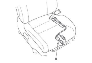
5. Disconnect the front passenger's seat wire harness 3P connector from the front passenger's seat belt buckle switch 3P connector (A).
6. Turn the ignition switch ON (II).
From the system selection menu on the HDS, select SRS, then select SRS again, then select PARAMETER INFORMATION, then Buckle Switch, Seat Position Sensor, and check the status on the HDS screen for FRONT RIGHT SEAT BELT BUCKLE SWITCH.
Is OPEN indicated on the HDS? YES-Replace the front passenger's seat belt buckle assembly, then clear the DTC.
NO-Short to ground in the front passenger's seat wire harness, front passenger's seat subharness, or floor wire harness; replace the faulty harness.
DTC 71-1x ("x" can be 0 thru 9 or A thru F): Open in Driver's Seat Position Sensor
NOTE: Before doing this troubleshooting procedure, review SRS Precautions and Procedures.
1. Erase the DTC memory.
2. Turn the ignition switch ON (II), and check that the SRS indicator comes on for about 6 seconds and then goes off.
Does the SRS indicator stay on, and is DTC 71-1x indicated? YES-Go to step 3.
NO-Intermittent failure, the system is OK at this time. Go to Troubleshooting Intermittent Failures. If another DTC is indicated, go to the DTC Troubleshooting Index.
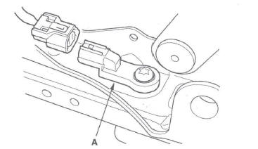
3. Check the connection between the seat position sensor harness 2P connector and the driver's seat position sensor.
4. Erase the DTC memory.
5. Read the DTC.
Is DTC 71-1x indicated? YES-Go to step 6.
NO-Intermittent failure, the system is OK at this time. Go to Troubleshooting Intermittent Failures. If another DTC is indicated, go to the DTC Troubleshooting Index.
6. Turn the ignition switch OFF. Disconnect the negative cable from the battery, and wait for 3 minutes.
7. Disconnect the seat position sensor harness 2P connector from the driver's seat position sensor (A).
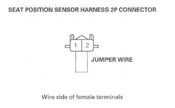
8. Connect the No.1 and No.2 terminals of the seat position sensor harness 2P connector with a jumper wire.
9. Disconnect both seat belt tensioner connectors (see step 7 on page 24-24) and both seat belt buckle tensioner connectors.
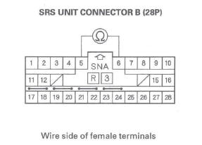
10. Disconnect SRS unit connector B (28P) from the SRS unit (see step 9 on page 24-24).
11. Check resistance between the No.5 and No.6 terminals of SRS unit connector B (28P). There should be 0-1.0 Ω.
Is the resistance as specified? YES-Faulty driver's seat position sensor or SRS unit; replace the driver's seat position sensor (see page 24-183). If the problem is still present, replace the SRS unit.
NO-Open in the floor wire harness, driver's seat wire harness, or the seat position sensor harness; replace the faulty harness.
READ NEXT:
 DTC 71-2x ("x" can be 0 thru 9 or A thru F):
Short in Driver's Seat Position Sensor
DTC 71-2x ("x" can be 0 thru 9 or A thru F):
Short in Driver's Seat Position Sensor
NOTE: Before doing this troubleshooting procedure,
review SRS Precautions and Procedures.
1. Erase the DTC memory.
2. Turn the ignition switch ON (II), and check that the
SRS indicator comes on for a
DTC 82-14: No Signal From the Front
Passenger's Weight Sensor (front inner side)
NOTE: Before doing this troubleshooting procedure,
review SRS Precautions and Procedures.
1. Erase the DTC memory.
2. Read the DTC.
Is DTC 82-14 indicated?
YES-Go to step 3.
NO-Intermittent failure
DTC 83-26: No Signal From the Front
Passenger's Weight Sensor (rear outer side)
NOTE: Before doing this troubleshooting procedure,
review SRS Precautions and Procedures.
1. Erase the DTC memory.
2. Read the DTC.
Is DTC 83-26 indicated?
YES-Go to step 3.
NO-Intermittent failur
SEE MORE:
DTC P0705: Short in Transmission Range
Switch Circuit (Multiple Shift-Position Input)
NOTE:
Before you troubleshoot, record all freeze data and any on-board
snapshot, and review General Troubleshooting Information.
This code is caused by an electrical circuit problem
and cannot be caused by a mechanical problem in the
transmission.
1. Clear the DTC with the HDS.
2. Start the
Steering Gearbox Removal
Special Tools Required
Ball joint remover, 28 mm 07MAC-SL0A202
Note these items during removal:
Using solvent and a brush, wash any oil and dirt off
the valve body unit, it's lines, and the end of the
steering gearbox. Blow dry with compressed air.
Be sure to remove the steering wheel before
d
