Honda CR-V: Cruise Control
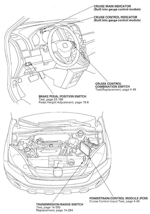
Component Location Index
- CRUISE MAIN INDICATOR
- CRUISE CONTROL INDICATOR
- CRUISE CONTROL COMBINATION SWITCH
- BRAKE PEDAL POSITION SWITCH
-
POWERTRAIN CONTROL MODULE (PCM)
-
TRANSMISSION RANGE SWITCH
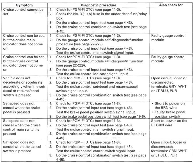
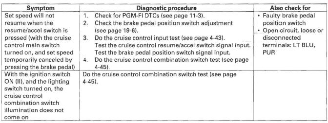
Symptom Troubleshooting Index
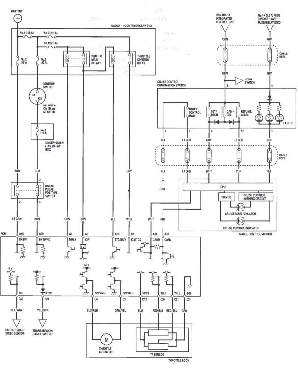
Circuit Diagram
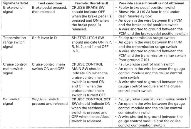
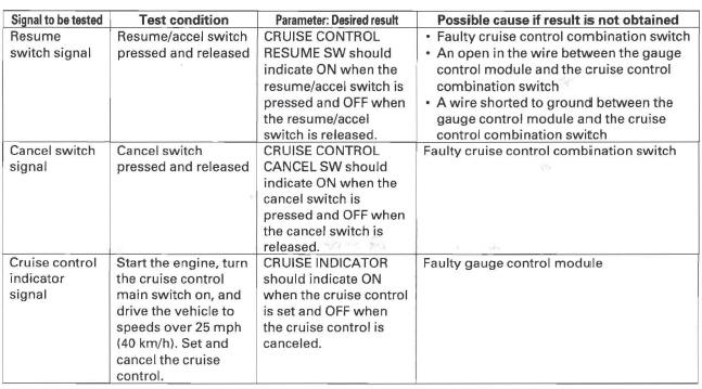
Cruise Control Input Test
1. Connect the Honda Diagnostic System (HDS) to the data link connector (DLC) (see step 2).
2. Turn the ignition switch ON (II).
3. Make sure the HDS communicates with the vehicle and the powertrain control module (PCM). If it doesn't, troubleshoot the DLC circuit.
4. Go to PGM-FI, and check for DTCs.
5. Do the following tests while monitoring parameters in the PGM-FI DATA LIST with the HDS.
NOTE: Intermittent failures are often caused by loose circuit connections. While monitoring cruise control inputs, flex their circuits, and note if any of the test results change.
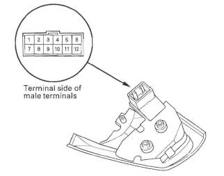
Cruise Control Combination Switch Test/Replacement
SRS components are located in this area. Review the SRS component locations and the precautions and procedures before doing repairs or service.
1. Remove the steering wheel.
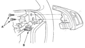
2. Remove the screws (A). Disconnect the 12P connector (B), then remove the cruise control combination switch.
3. Check for continuity between the terminals in each switch position according to the table.
- If there is continuity, and it matches the table, but switch failure occurred on the cruise control input test, check and repair the wire harness on the switch circuit.
- If there is no continuity in one or more positions, replace the switch.
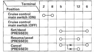
4. Check for continuity between the terminals in according to the table.
- If there is continuity, and it matches the table, check and repair the wire harness on the switch circuit.
- If there is no continuity in one or more positions, replace the switch.
Engine Electrical
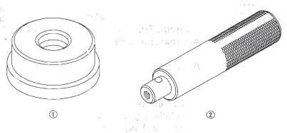
Special Tools

-
Attachment, 42 x 47 mm
-
Driver
READ NEXT:
 Engine Removal
Universal eyelet 07AAK-SNAA120
Engine hanger adapter VSB02C000015 *
Front subframe adapter VSB02C000016 *
CR-V engine hanger adapter VSB02C000032 *
Engine support hanger, A and Reds AAR-T-12566
SEE MORE:
CKP Pulse Plate Replacement
1. Remove the front wheels.
2. Remove the splash shield (see step 21).
3. Remove the drive belt.
4. Remove the cylinder head cover.
5. Set the No.1 piston at top dead center (TDC). The
punch mark on the variable valve timing control
(VTC) actuator and the punch mark on the exhaust
camshaft sproc
Head Restraints
See page for important safety
information and a warning about
improperly positioning head restraints.
Your vehicle is equipped with head
restraints in all seating positions to
help protect you and your
passengers from the likelihood of
whiplash and other injuries.
They are most eff
