Honda CR-V: DTC 71-2x ("x" can be 0 thru 9 or A thru F): Short in Driver's Seat Position Sensor
NOTE: Before doing this troubleshooting procedure, review SRS Precautions and Procedures.
1. Erase the DTC memory.
2. Turn the ignition switch ON (II), and check that the SRS indicator comes on for about 6 seconds and then goes off.
Does the SRS indicator stay on, and is DTC 71-2x indicated? YES-Go to step 3.
NO-Intermittent failure, the system is OK at this time. Go to Troubleshooting Intermittent Failures. If another DTC is indicated, go to the DTC Troubleshooting Index.
3. Turn the ignition switch OFF. Disconnect the negative cable from the battery, and wait for 3 minutes.
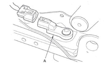
4. Disconnect the seat position sensor harness 2P connector from the driver's seat position sensor (A).
5. Reconnect the negative cable to the battery.
6. Erase the DTC memory.
7. Read the DTC.
Is DTC 71-2x indicated? YES-Go to step 8.
NO-Faulty driver's seat position sensor; replace the driver's seat position sensor
8. Turn the ignition switch OFF. Disconnect the negative cable from the battery, and wait for 3 minutes.
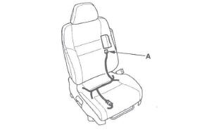
9. Disconnect both seat belt tensioner connectors (see step 7) and both seat belt buckle tensioner connectors (see step 8).
10. Disconnect SRS unit connector B (28P) from the SRS unit (see step 9).
11. Check resistance between the No.5 and No.6 terminals of SRS unit connector B (28P). There should be an open circuit (ohmmeter reads OL) or at least 1 M Ω.
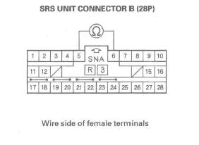
Is the resistance as specified? YES-Go to step 12.
NO-Short in the floor wire harness, driver's seat wire harness, or the seat position sensor harness; replace the faulty harness.
12. Check resistance between the No.5 terminal of SRS unit connector B (28P) and body ground, and between the No.6 terminal and body ground.
There should be an open circuit (ohmmeter reads OL) or at least 1 M Ω.
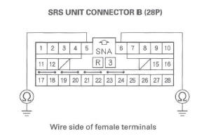
Is the resistance as specified? YES-Faulty driver's seat position sensor or the SRS unit; replace the driver's seat position sensor (see page 24-183). If the problem is still present, replace the SRS unit.
NO-Short in the floor wire harness, driver's seat wire harness, or the seat position sensor harness; replace the faulty harness.
DTC 81-61, 85-61: No Signal From ODS Unit
DTC 81-62, 85-62: Non-Stipulated Response Data
NOTE: Before doing this troubleshooting procedure, review SRS Precautions and Procedures.
1. Make sure nothing is on the front passenger's seat.
2. Erase the DTC memory.
3. Read the DTC.
Is DTC 81-61, 85-61, 81-62, or 85-62 indicated? YES-Go to step 4.
NO-Intermittent failure, the system is OK at this time. Go to Troubleshooting Intermittent Failures. If another DTC is indicated, go to the DTC Troubleshooting Index.
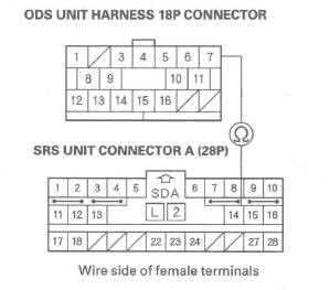
4. Check the connection between the ODS unit harness 18P connector and the ODS unit (see step 4).
Is the connection OK? YES-Go to step 6.
NO-Repair the poor connection and retest. If DTC 85-61 or 85-62 is still present, go to step 5.
5. Turn the ignition switch OFF.
6. Check the No.9 (7.5 A) fuse in the under-dash fuse/ relay box.
Is the fuse OK? YES-Go to step 7.
NO-Replace the fuse, then turn the ignition switch ON (II). If the fuse blows again, check for a short in the No.9 (7.5 A) fuse circuit (dashboard wire harness, floor wire harness, front passenger's seat subharness, or ODS unit harness).
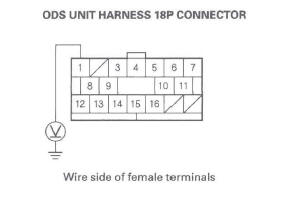
7. Disconnect the ODS unit harness 18P connector (A) from the ODS unit.
8. Turn the ignition switch ON (II).
9. Check for voltage between the No.1 terminal of the ODS unit harness 18P connector and body ground.
There should be battery voltage.
Is there battery voltage? YES-Go to step 10.
NO-Open in the dashboard wire harness, floor wire harness, front passenger's seat subharness, or ODS unit harness; replace the faulty harness.
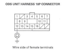
10. Turn the ignition switch OFF.
11. Check resistance between the No. 12 terminal of ODS unit harness 18P connector and body ground. There should be 0-1.0 Ω.
Is the resistance as specified? YES-Go to step 12.
NO-Open in the ODS unit harness, front passenger's seat subharness, floor wire harness, or poor ground connection at G552.
If G552 is OK, replace the faulty harness.
12. Turn the ignition switch OFF. Disconnect the negative cable from the battery, and wait for 3 minutes.
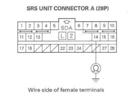
13. Disconnect SRS unit connector A (28P) from the SRS unit (see step 9).
14. Check resistance between the No. 14 terminal of SRS unit connector A (28P) and body ground. There should be an open circuit (ohmmeter reads OL) or at least 1 M Ω.
Is the resistance as specified? YES-Go to step 15.
NO-Short to ground in the dashboard wire harness, floor wire harness, front passenger's seat subharness, or ODS unit harness; replace the faulty harness.
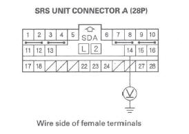
15. Turn the ignition switch ON (II), and measure the voltage between the No. 14 terminal of SRS unit connector A (28P) and body ground. There should be 0.5 V or less.
Is the voltage as specified? YES-Go to step 16.
NO-Short to power in the dashboard wire harness, floor wire harness, front passenger's seat subharness, or ODS unit harness; replace the faulty harness.
16. Check resistance between the No. 14 terminal of SRS unit connector A (28P) and the No.7 terminal of the ODS unit harness 18P connector. There should be 0-1.0 Ω.
Is the resistance as specified? YES-Faulty ODS unit or SRS unit; replace the ODS unit. If the problem is still present, replace the SRS unit.
NO-Open in the dashboard wire harness, floor wire harness, front passenger's seat subharness, or ODS unit harness; replace the faulty harness.
DTC 81-71, 81-78: ODS Unit Does Not Calibrate
DTC 85-71, 85-78: ODS Unit Does Not Initialize
NOTE: Before doing this troubleshooting procedure, review SRS Precautions and Procedures.
1. Erase the DTC memory.
2. Turn the ignition switch ON (II), and check that the SRS indicator comes on for about 6 seconds and then goes off.
Does the SRS indicator stay on, and is 81-71, 81-78, 85-71, or 85-78 indicated? YES-Go to step 3.
NO-Intermittent failure, the system is OK at this time. Go to Troubleshooting Intermittent Failures. If another DTC is indicated, go to the DTC Troubleshooting Index.
3. Initialize the ODS unit or calibrate the ODS unit.
4. Turn the ignition switch ON (II), and check that the SRS indicator comes on for about 6 seconds and then goes off.
Does the SRS indicator go off? YES-The system is OK.
NO-Replace the ODS unit.
DTC 81-4x, 81-5x ("x" can be 0 thru 9 or A thru F), 81-63, 81-64: Internal Failure of the ODS Unit
NOTE: Before doing this troubleshooting procedure, review SRS Precautions and Procedures.
1. Erase the DTC memory.
2. Turn the ignition switch ON (II), and check that the SRS indicator comes on for about 6 seconds and then goes off.
Does the SRS indicator stay on, and is DTC 81-4x, 81-5x, 81-63, or 81-64 indicated? YES-Replace the ODS unit (see page 24-181). If the DTC returns, replace the SRS unit.
NO-Intermittent failure, the system is OK at this time. Go to Troubleshooting Intermittent Failures. If another DTC is indicated, go to the DTC Troubleshooting Index.
DTC 81-79: Front Passenger's Weight Sensors Drift Check Failure
NOTE: Before doing this troubleshooting procedure, review SRS Precautions and Procedures.
1. Erase the DTC memory.
2. Turn the ignition switch ON (II), and check that the SRS indicator comes on for about 6 seconds and then goes off.
Does the SRS indicator stay on, and is DTC 81-79 indicated? YES-Go to step 3.
NO-Intermittent failure, the system is OK at this time. Go to Troubleshooting Intermittent Failures. If another DTC is indicated, go to the DTC Troubleshooting Index.
3. Turn the ignition switch OFF.
4. Make sure nothing is on the front passenger's seat.
5. Turn the ignition switch ON (II), and check that the SRS indicator comes on for about 6 seconds and then goes off.
Does the SRS indicator go off? YES-The system is OK.
NO-Remove the front passenger's seat assembly (see page 20-118) and the front passenger's weight sensors (see page 24-179), then reinstall them.
Calibrate the ODS unit. Retry the troubleshooting. If DTC 81-79 is still present, replace the front passenger's weight sensors.
READ NEXT:
 DTC 82-14: No Signal From the Front
Passenger's Weight Sensor (front inner side)
DTC 82-14: No Signal From the Front
Passenger's Weight Sensor (front inner side)
NOTE: Before doing this troubleshooting procedure,
review SRS Precautions and Procedures.
1. Erase the DTC memory.
2. Read the DTC.
Is DTC 82-14 indicated?
YES-Go to step 3.
NO-Intermittent failure
DTC 83-26: No Signal From the Front
Passenger's Weight Sensor (rear outer side)
NOTE: Before doing this troubleshooting procedure,
review SRS Precautions and Procedures.
1. Erase the DTC memory.
2. Read the DTC.
Is DTC 83-26 indicated?
YES-Go to step 3.
NO-Intermittent failur
Symptom Troubleshooting
SRS indicator does not come on
1. Connect the HDS to the DLC.
2. Turn the ignition switch ON (II).
3. Make sure the HDS communicates with the vehicle and the SRS unit. If it does
not communicate,
SEE MORE:
Automatic Transmission Fluid
Check the fluid level with the engine
at normal operating temperature.
1. Park the vehicle on level ground.
Start the engine, let it run until the
radiator fan comes on, then shut
off the engine. For accurate
results, wait about 60 seconds (but
no longer than 90 seconds) before
doing
Engine Compression Inspection
NOTE: After this inspection, you must reset the
powertrain control module (PCM), otherwise the PCM
will continue to stop the injectors from functioning.
Select PCM reset using the Honda Diagnostic System
(HDS).
1. Warm up the engine to normal operating
temperature (cooling fan comes on).
2. Turn t
