Honda CR-V: DTC 83-26: No Signal From the Front Passenger's Weight Sensor (rear outer side)
NOTE: Before doing this troubleshooting procedure, review SRS Precautions and Procedures.
1. Erase the DTC memory.
2. Read the DTC.
Is DTC 83-26 indicated? YES-Go to step 3.
NO-Intermittent failure, the system is OK at this time. Go to Troubleshooting Intermittent Failures.
3. From INSPECTION menu on the HDS, select SWS DTC CHECK.
Is another DTC also indicated? YES-
- DTC 26-11: Short to power in the ODS unit harness; replace the ODS unit harness.
- DTC 26-12: Go to step 4.
- DTC 26-13: Go to step 11.
- DTC 26-14: Go to step 19.
NO-Intermittent failure, the system is OK at this time. Go to Troubleshooting Intermittent Failures.
4. Turn the ignition switch OFF.
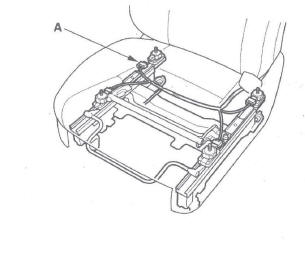
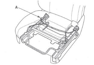
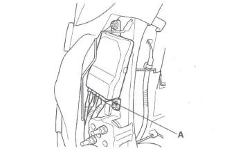
5. Disconnect the ODS unit harness 3P connector (A) from the front passenger's weight sensor (rear outer side).
6. Read the DTC.
Is DTC 26-12 indicated? YES-Go to step 7.
NO-Faulty front passenger's weight sensor (rear outer side); replace the front passenger's weight sensor.
7. Turn the ignition switch OFF.
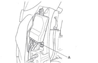
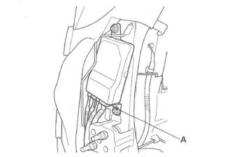
8. Disconnect the ODS unit harness 18P connector (A) from the ODS unit.
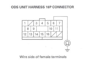
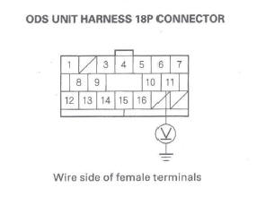
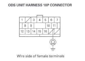
9. Check resistance between the No. 6 terminal of the ODS unit harness 18P connector and body ground.
There should be an open circuit (ohmmeter reads OL) or at least 1 M Ω.
Is the resistance as specified? YES-Go to step 10.
NO-Short to ground in the ODS unit harness; replace the ODS unit harness.
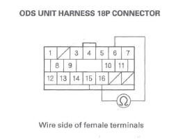
10. Check resistance between the No.6 terminal and No. 16 terminal of the ODS unit harness 18P connector. There should be an open circuit (ohmmeter reads OL) or at least 1 M Ω.
Is the resistance as specified? YES-Faulty ODS unit; replace the ODS unit.
NO-Short to ground in the ODS unit harness; replace the ODS unit harness.
11. Turn the ignition switch OFF.
12. Swap the connections between the front passenger's weight sensor (rear outer side) and the front passenger's weight sensor (front outer side).
13. Read the DTC.
Is DTC 26-13 indicated? YES-Go to step 14.
NO-Faulty front passenger's weight sensor (rear outer side); replace the front passenger's weight sensor.
14. Turn the ignition switch OFF.
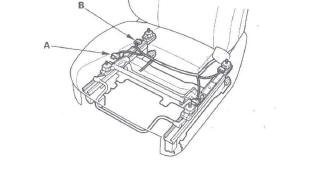
15. Disconnect the front passenger's weight sensor (rear outer side) connector (A) and front passenger's weight sensor (front outer side) connector (B).
16. Disconnect the ODS unit harness 18P connector (A) from the ODS unit.
17. Turn the ignition switch ON (II).
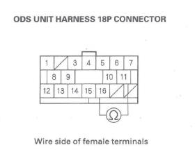
18. Check for voltage between the No. 11 terminal of the ODS unit harness 18P connector and body ground. There should be 1 V or less.
Is the voltage as specified? YES-Faulty ODS unit; replace the ODS unit.
NO-Short to power-in the ODS unit harness; replace the ODS unit harness.
19. Turn the ignition switch OFF.
20. Disconnect the ODS unit harness 3P connector (A) from the front passenger's weight sensor (rear outer side).
21. Read the DTC.
Is DTC 26-14 indicated? YES-Go to step 22.
NO-Faulty front passenger's weight sensor (rear outer side); replace the front passenger's weight sensor.
22. Turn the ignition switch OFF.
23. Disconnect the ODS unit harness 18P connector (A) from the ODS unit.
24. Check resistance between the No. 11 terminal of the ODS unit harness 18P connector and body ground. There should be an open circuit (ohmmeter reads OL) or at least 1 M Ω.
Is the resistance as specified? YES-Go to step 25.
NO-Short to ground in the ODS unit harness; replace the ODS unit harness.
25. Check resistance between the No. 11 terminal and No. 16 terminal of front passenger's seat wire harness 18P connector. There should be an open circuit (ohmmeter reads OL) or at least 1 M Ω.
Is the resistance as specified? YES-Faulty ODS unit; replace the ODS unit.
NO-Short in the ODS unit harness; replace the ODS unit harness.
DTC 85-4x, 85-5x ("x" can be 0 thru 9 or A thru F), 85-63, 85-64: Internal Failure of the ODS Unit
NOTE:
- An incorrect ODS unit can cause DTC 85-63.
- Before doing this troubleshooting procedure, review SRS Precautions and Procedures.
1. Erase the DTC memory.
2. Turn the ignition switch ON (II), and check that the SRS indicator comes on for about 6 seconds and then goes off.
Does the SRS indicator stay on, and is DTC85-4x, 85-5x, 85-63, or 85-64 indicated? YES-Go to step 3.
NO-Intermittent failure, the system is OK at this time. Go to Troubleshooting Intermittent Failures. If another DTC is indicated, go to the DTC Troubleshooting Index.
3. Initialize the ODS unit.
4. Turn the ignition switch ON (II), and check that the SRS indicator comes on for about 6 seconds and then goes off.
Does the SRS indicator go off? YES-The system is OK.
NO-Replace the ODS unit and retest.
DTC 85-79: OPDS Sensor Drift Check Failure
NOTE: Before doing this troubleshooting procedure, review SRS Precautions and Procedures.
1. Erase the DTC memory.
2. Turn the ignition switch ON (II), and check that the SRS indicator comes on for about 6 seconds and then goes off.
Does the SRS indicator stay on, and is DTC 85-79 indicated? YES-Turn the ignition switch OFF, and go to step 3.
NO-Intermittent failure, the system is OK at this time. Go to Troubleshooting Intermittent Failures. If another DTC is indicated, go to the DTC Troubleshooting Index.
3. Make sure nothing is on the front passenger's seat.
4. Turn the ignition switch ON (II), and check that the SRS indicator comes on for about 6 seconds and then goes off.
Does the SRS indicator go off? YES-The system is OK.
NO-Go to step 5.
5. Initialize the ODS unit.
6. Turn the ignition switch ON (II), and check that the SRS indicator comes on for about 6 seconds and then goes off.
Does the SRS indicator go off? YES-The system is OK.
NO-Replace the ODS unit (see page 24-181) and retest. If the problem is still present, replace the OPDS sensor/seat-back.
DTC 86-1x ("X" can be 0 thru 9 or A thru F): Faulty OPDS Seat-Back Sensor
DTC 86-2x ("X" can be 0 thru 9 or A thru F): Faulty OPDS Seat Support Sensor
NOTE: Before doing this troubleshooting procedure, review SRS Precautions and Procedures.
1. Erase the DTC memory.
2. Turn the ignition switch ON (II), and check that the SRS indicator comes on for about 6 seconds and then goes off.
Does the SRS indicator stay on, and is DTC 86-1x or 86-2x indicated? YES-Go to step 3.
NO-Intermittent failure, the system is OK at this time. Go to Troubleshooting Intermittent Failures. If another DTC is indicated, go to the DTC Troubleshooting Index.
NOTE: Aftermarket devices (fluorescent lights, laptop computers, etc.) used near the front passenger's seat-back can interfere with the seatback sensors and cause a false DTC 86-1x or 86-2x.
If one of these devices was used, erase the DTC, operate the device near the seat-back, and recheck for DTCs. If DTC 86-1x or 86-2x is set, erase it, and do not use the device near the seat-back.
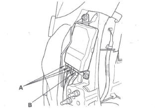
3. Check the connection at the OPDS sensor harness connectors (A) and the ODS unit connector (B).
Is the connection OK? YES-Go to step 4.
NO-Repair the poor connection, and clear the DTC.
4. Replace the OPDS sensor/seat-back foam (see page 20-125), and initialize the ODS.
5. Erase the DTC memory, then check for DTC 86-1 x or 86-2x.
Is DTC 86-1x or 86-2x indicated? YES-Replace the ODS unit.
NO-The system is OK.
DTC 92-1x ("x" can be 0 thru 9 or A thru F): Short to Power in the Passenger's Airbag Cutoff Indicator
NOTE: Before doing this troubleshooting procedure, review SRS Precautions and Procedures.
1. Erase the DTC memory.
2. Turn the ignition switch ON (II), and check that the SRS indicator comes on for about 6 seconds and then goes off.
Does the SRS indicator stay on, and is DTC 92-1x indicated?.
YES-Go to step 3.
NO-Intermittent failure, the system is OK at this time. Go to Troubleshooting Intermittent Failures. If another DTC is indicated, go to the DTC Troubleshooting Index.
3. Disconnect the passenger's airbag cutoff indicator 6P connector.
4. Turn the ignition switch OFF. Disconnect the negative cable from the battery, and wait for 3 minutes.
5. Disconnect SRS unit connector A (28P) from the SRS unit (see step 8 on page 24-24).
6. Reconnect the negative cable to the battery.
7. Turn the ignition switch ON (II).
8. Check for voltage between the No. 13 terminal of SRS unit connector A (28P) and body ground. There should be 0.5 V or less.
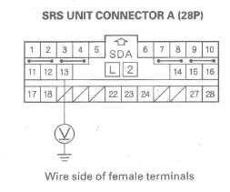
Is the voltage as specified? YES-Faulty SRS unit or passenger's airbag cutoff indicator; replace the passenger's airbag cutoff indicator. If the problem is still present, replace the SRS unit.
NO-Short to power in the dashboard wire harness; replace the dashboard wire harness.
DTC 92-2x ("x" can be 0 thru 9 or A thru F): Open or Short to Ground in the Passenger's Airbag Cutoff Indicator
NOTE: Before doing this troubleshooting procedure, review SRS Precautions and Procedures.
1. Erase the DTC memory.
2. Turn the ignition switch ON (II), and check that the SRS indicator comes on for about 6 seconds and then goes off.
Does the SRS indicator stay on, and DTC 92-2x indicated? YES-Go to step 3.
NO-Intermittent failure, the system is OK at this time. Go to Troubleshooting Intermittent Failures. If another DTC is indicated, go to the DTC Troubleshooting Index.
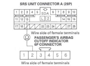
3. Disconnect the passenger's airbag cutoff indicator 6P connector.
4. Turn the ignition switch OFF. Disconnect the negative cable from the battery, and wait for 3 minutes.
5. Disconnect SRS unit connector A (28P) from the SRS unit (see step 8 on page 24-24).
6. Check resistance between the No.2 terminal of the passenger's airbag cutoff indicator 6P connector and the No. 13 terminal of SRS unit connector A (28P). There should be 0-1.0 Ω.
Is the resistance as specified? YES-Go to step 7.
NO-Open in the dashboard wire harness; replace the dashboard wire harness.
7. Check resistance between the No. 13 terminal of the SRS unit connector A (28P) and body ground.
There should be an open circuit (ohmmeter reads OL) or at least 1 M Ω.
Is the resistance as specified? YES-Replace the passenger's airbag cutoff indicator. If the problem is still present, replace the SRS unit.
NO-Short to ground in the dashboard wire harness; replace the dashboard wire harness.
DTC A1-1x ("X" can be 0 thru 9 or A thru F): Faulty Power supply (VA Line)
NOTE: Before doing this troubleshooting procedure, review SRS Precautions and Procedures.
1. Erase the DTC memory.
2. Turn the ignition switch ON (II), and check that the SRS indicator comes on for about 6 seconds and then goes off.
3. Read the DTC.
Is DTC A1-1x indicated? YES-Go to step 4.
NO-Intermittent failure, the system is OK at this time. Go to Troubleshooting Intermittent Failures. If another DTC is indicated, go to the DTC Troubleshooting Index.
4. Turn the ignition switch OFF.
5. Check the No.9 (7.5 A) fuse in the under-dash fuse/ relay box.
Is the fuse OK? YES-Go to step 6.
NO-Replace the fuse, then turn the ignition switch ON (II). If the fuse blows again, check for a short in the No.9 (7.5 A) fuse circuit (dashboard wire harness, floor wire harness, front passenger's seat subharness, or front passenger's seat wire harness).
6. Disconnect the negative cable from the battery, and wait for 3 minutes.
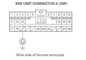
7. Disconnect the SRS unit connector A (28P) from the SRS unit (see step 8 on page 24-24).
8. Turn the ignition switch ON (II).
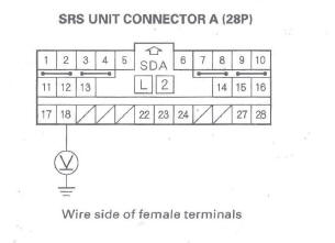
9. Connect a voltmeter between the No. 17 terminal of SRS unit connector A (28P) and body ground. Turn the ignition switch ON (II), and measure Voltage.
There should be battery voltage when the ignition is on.
Is there battery voltage? YES-Faulty SRS unit or poor connection at SRS unit connector (A) 28P and the SRS unit. Check the connection between the connector and the SRS unit. If the connection is OK, replace the SRS unit.
NO-Go to step 10.
10. Turn the ignition switch OFF.
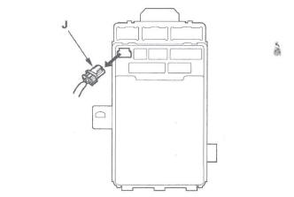
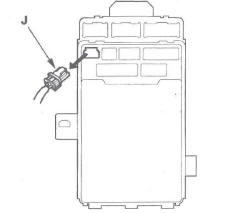
11. Disconnect under-dash fuse/relay box connector J (4P).
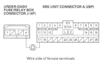
12. Check resistance between the No.4 terminal of under-dash fuse/relay box connector J. (4P) and the No. 17 terminal of SRS unit connector A (28P).
There should be 0-1.0 Ω.
Is the resistance as specified? YES-Open in the under-dash fuse/relay box or poor contact between connector J (4P) and the under-dash fuse/relay box; check the connection. If the connection is OK, replace the under-dash fuse/ relay box.
NO-Open in the dashboard wire harness; replace the dashboard wire harness.
DTC A2-1x ("x" can be 0 thru 9 or A thru F): Faulty Power Supply (VB Line)
NOTE: Before doing this troubleshooting procedure, review SRS Precautions and Procedures.
1. Check the No. 11 (10 A) fuse in the under-dash fuse/ relay box.
Is the fuse OK? YES-Go to step 11.
NO-Go to step 2.
2. Replace the No. 11 (10 A) fuse.
3. Turn the ignition switch ON (II) and wait for 30 seconds. Then turn the ignition switch OFF.
4. Check the No. 11 (10 A) fuse.
Is the fuse OK? YES-The system is OK at this time.
NO-Go to step 5.
5. Replace the No. 11 (10 A) fuse.
6. Turn the ignition switch OFF. Disconnect the negative cable from the battery, and wait for 3 minutes.
7. Disconnect SRS unit connector A (28P) from the SRS unit (see step 8 on page 24-24).
8. Reconnect the negative cable to the battery.
9. Turn the ignition switch ON (II), and wait for 30 seconds. Then turn the ignition switch OFF.
10. Check the No. 11 (10 A) fuse.
Is the fuse OK? YES-Short to ground in the SRS unit; replace the SRS unit.
NO-Short to ground in the dashboard wire harness or in the under-dash fuse/relay box No. 11 (10 A) fuse line; replace the dashboard wire harness. If the problem is still there, replace the under-dash fuse/relay box.
11. Turn the ignition switch OFF. Disconnect the negative cable from the battery, and wait for 3 minutes.
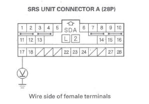
12. Disconnect SRS unit connector A (28P) from the SRS unit (see step 8 on page 24-24).
13. Reconnect the negative cable to the battery.
14. Connect a voltmeter between the No. 18 terminal of SRS unit connector A (28P) and body ground. Turn the ignition switch ON (II), and measure voltage.
There should be battery voltage when the ignition on.
Is there battery voltage? YES-Faulty SRS unit or poor connection at SRS unit connector A (28P) and the SRS unit; check the connection. If the connection is OK, replace the SRS unit.
NO-Go to step 15.
15. Turn the ignition switch OFF.
16. Disconnect under-dash fuse/relay box connector J (4P).
17. Check resistance between the No.1 terminal of the under-dash fuse/relay box connector J (4P) and the No. 18 terminal of SRS unit connector A (28P).
There should be 0-1.0 Ω.
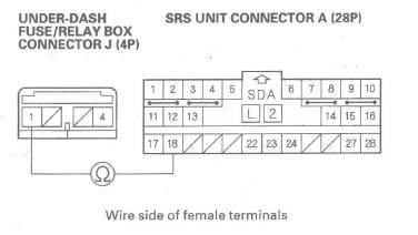
Is the resistance as specified? YES-Open in the under-dash fuse/relay box or poor connection between connector J (4P) and the under-dash fuse/relay box; check the connection. If the connection is OK, replace the under-dash fuse/ relay box.
NO-Open in the dashboard wire harness; replace the dashboard wire harness.
READ NEXT:
 Symptom Troubleshooting
SRS indicator does not come on
1. Connect the HDS to the DLC.
2. Turn the ignition switch ON (II).
3. Make sure the HDS communicates with the vehicle and the SRS unit. If it does
not communicate,
Component Replacement/Inspection After
Deployment
NOTE:
Before doing any SRS repairs, use the HDS SRS
menu method to check for DTCs; refer to the DTC
Troubleshooting Index for the less obvious deployed
parts (seat belt tensioners, front impact s
Driver's Airbag Replacement
Removal
1. Disconnect the negative cable from the battery and
wait at least 3 minutes before beginning work.
2. Remove the access panel (A) from the steering
wheel, then disconnect the driver's airba
SEE MORE:
System Description
Overview
The navigation system is a highly sophisticated, hybrid locating system.
The navigation unit uses global positioning system (GPS) satellite signals,
internal yaw and vehicle speed inputs, and
a map database to show you where you are and to help guide you to a desired
destination.
The na
No sound is heard from speaker(s) (display is
normal) (with navigation)
NOTE:
Set the fader and balance positions to the center.
Before doing symptom troubleshooting, do the
power switch will not turn ON troubleshooting.
1. Check that the volume button is not set to the MIN
level.
Is it at MIN level? YES-Raise the volume level, and recheck the function.
NO-Go to
