Honda CR-V: Driver's Airbag Replacement
Removal
1. Disconnect the negative cable from the battery and wait at least 3 minutes before beginning work.
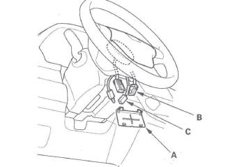
2. Remove the access panel (A) from the steering wheel, then disconnect the driver's airbag 4P connector (B) and horn switch 1P connector (C) from the cable reel.
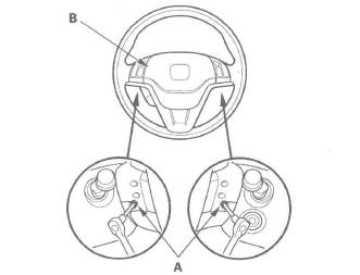
3. Using a TORX T30 bit, remove the two TORX bolts (A).
4. Remove the driver's airbag (B).
Installation
1. Connect the horn switch connector (1P) (A) to the driver's airbag (B).
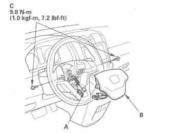
2. Place the driver's airbag in the steering wheel, and secure it with new TORX bolts (C).
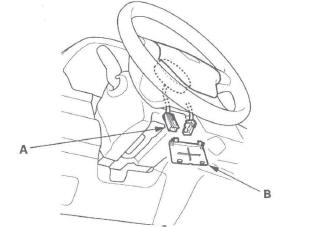
3. Connect the cable reel 4P connector (A) to the driver's airbag 4P connector, then install the access panel (B) on the steering wheel.
4. Connect the negative cable from the battery.
5. After installing the airbag, confirm proper system operation:
- Turn the ignition switch ON (II); the SRS indicator should come on for about 6 seconds and then go off.
- Make sure the horn works.
READ NEXT:
 Front Passenger's Airbag Replacement
Removal
1. Disconnect the negative cable from the battery, and
wait at least 3 minutes before beginning work.
2. Remove the passenger's vent panel.
3. Remove the dashboard center upper panel.
4. Re
Side Airbag Replacement
NOTE: Review the seat replacement procedure before doing repairs or service.
Removal
1. Disconnect the negative cable from the battery, and
wait at least 3 minutes before beginning work.
2. Disconnec
Airbag and Tensioner Disposal
Special Tools Required
Deployment tool 07HAZ-SG00500
Before scrapping any airbags, side airbags, side curtain
airbags, seat belt tensioners; or lap belt tensioner
(including those in a whole vehicle t
SEE MORE:
To Change or Select Files
Use the SKIP button while a USB
flash memory device is playing to
change files.
SKIP - Each time you press and
release
(preset 6), the player
skips forward to the beginning of the
next file. Press and release
(preset 5), to skip backward
to
the beginning of the current file
General Troubleshooting Information
System Indicator locations
The system has two indicators.
The low pressure indicator (A)
The TPMS indicator (B)
How TPMS Works
The TPMS (tire pressure monitoring system) has a low
pressure indicator, and a TPMS indicator. When the
TPMS control unit detects low pressure in a tire, or a
problem i
