Honda CR-V: DTC 28-3x ("x" can be 0 thru 9 or A thru F): Short to Another Wire or Decreased Resistance in Front Passenger's Seat Belt Buckle Tensioner
Special Tools Required
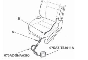
- SRS inflator simulator 07SAZ-TB4011A
- SRS simulator lead K 070AZ-SNAA200
NOTE: Before doing this troubleshooting procedure, review SRS Precautions and Procedures.
1. Erase the DTC memory.
2. Turn the ignition switch ON (II), and check that the SRS indicator comes on for about 6 seconds and then goes off.
Does the SRS indicator stay on, and is DTC 28-3x indicated? YES-Go to step 3.
NO-Intermittent failure, the system is OK at this time. Go to Troubleshooting Intermittent Failures. If another DTC is indicated, go to the DTC Troubleshooting Index.
3. Turn the ignition switch OFF. Disconnect the negative cable from the battery, and wait for 3 minutes.
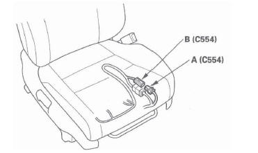
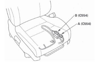
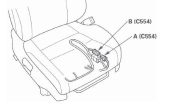
4. Disconnect the front passenger's seat subharness 4P connector (A) from the front passenger's seat belt buckle tensioner connector (B).

5. Connect the SRS inflator simulator (2 Ω connectors) and simulator lead K to front passenger's seat subharness connector.
6. Reconnect the negative cable to the battery.
7. Erase the DTC memory.
8. Read the DTC.
Is DTC 28-3x indicated? YES-Go to step 9.
NO-Short in the front passenger's seat belt buckle tensioner; replace the front passenger's seat belt buckle.
9. Turn the ignition switch OFF. Disconnect the negative cable from the battery, and wait for 3 minutes.
10. Disconnect both seat belt tensioner 4P connectors (see step 7) and the driver's seat belt buckle tensioner 4P connector (see step 8).
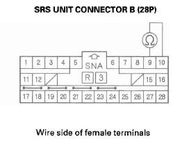
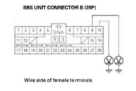
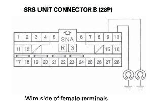
11. Disconnect SRS unit connector B (28P) from the SRS unit (see step 9).
12. Disconnect the simulator lead from the front passenger's seat subharness.
13. Check resistance between the No.9 and No. 10 terminals of SRS unit connector B (28P). There should be an open circuit (ohmmeter reads OL) or at least 1 M Ω.
Is the resistance as specified? YES-Faulty SRS unit or poor connection at SRS unit connector B (28P) and the SRS unit. Check the connection; if the connection is OK, replace the SRS unit.
NO-Go to step 14.
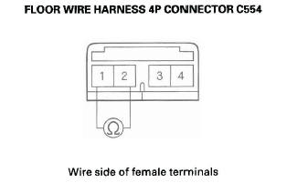
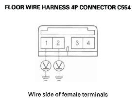
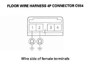
14. Disconnect floor wire harness 4P connector C554 (A) from front passenger's seat subharness 4P connector C554 (B).
15. Check resistance between the No.1 and No.2 terminal of floor wire harness 4P connector C554.
There should be an open circuit (ohmmeter reads OL) or at least 1 M Ω.
Is the resistance as specified? YES-Short to another wire in front passenger's seat subharness; replace the front passenger's seat subharness.
NO-Short to another wire in floor wire harness; replace the floor wire harness.
DTC 28-8x ("X" can be 0 thru 9 or A thru F): Short to Power in Front Passenger's Seat Belt Buckle Tensioner
Special Tools Required
- SRS inflator simulator 07SAZ-TB4011A
- SRS simulator lead K 070AZ-SNAA200
NOTE: Before doing this troubleshooting procedure, review SRS Precautions and Procedures.
1. Erase the DTC memory.
2. Turn the ignition switch ON (II), and check that the SRS indicator comes on for about 6 seconds and then goes off.
Does the SRS indicator stay on, and is DTC 28-8x indicated? YES-Go to step 3.
NO-Intermittent failure, the system is OK at this time. Go to Troubleshooting Intermittent Failures. If another DTC is indicated, go to the DTC Troubleshooting Index.
3. Turn the ignition switch OFF. Disconnectthe negative cable from the battery, and wait for 3 minutes.
4. Disconnect the front passenger's seat subharness 4P connector (A) from the front passenger's seat belt buckle tensioner connector (B).
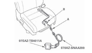
5. Connect the SRS inflator simulator (2 Ω connectors) and simulator lead K to front passenger's seat subharness connector.
6. Reconnect the negative cable to the battery.
7. Erase the DTC memory.
8. Read the DTC.
Is DTC 28-8x indicated? YES-Go to step 9.
NO-Short to power in the front passenger's seat belt buckle tensioner; replace the front passenger's seat belt buckle.
9. Turn the ignition switch OFF. Disconnect the negative cable from the battery, and wait for 3 minutes.
10. Disconnect both seat belt tensioner 4P connectors (see step 7) and the driver's seat belt buckle tensioner 4P connector (see step 8).
11. Disconnect SRS unit connector B (28P) from the SRS unit (see step 9).
12. Disconnect the simulator lead from the front passenger's seat subharness.
13. Reconnect the negative cable to the battery.
14. Turn the ignition switch ON (II).
15. Check for voltage between the No.9 terminal of SRS unit connector B (28P) and body ground, and the No. 10 terminal and body ground. There should be 0.5 V or less.
Is the voltage as specified? YES-Faulty SRS unit or poor connection at SRS unit connector B (28P) and the SRS unit. Check the connection; if the connection is OK, replace the SRS unit.
NO-Go to step 16.
16. Turn the ignition switch OFF.
17. Disconnect floor wire harness 4P connector C554 (A) from front passenger's seat subharness 4P connector C554 (B).
18. Check for voltage between the No.1 terminal of floor wire harness 4P connector C554 and body ground, and between the No.2 terminal and body ground. There should be less than 0.5 V.
Is the voltage as specified? YES-Short to power in front passenger's seat subharness; replace the front passenger's seat subharness.
NO-Short to power in floor wire harness; replace the floor wire harness.
DTC 28-9x ("X" can be 0 thru 9 or A thru F): Short to Ground in Front Passenger's Seat Belt Buckle Tensioner
Special Tools Required
- SRS inflator simulator 07SAZ-TB4011A
- SRS simulator lead K 070AZ-SNAA200
NOTE: Before doing this troubleshooting procedure, review SRS Precautions and Procedures.
1. Erase the DTC memory.
2. Turn the ignition switch ON (II), and check that the SRS indicator comes on for about 6 seconds and then goes off.
Does the SRS indicator stay on, and is DTC 28-9x indicated? YES-Go to step 3.
NO-Intermittent failure, the system is OK at this time. Go to Troubleshooting Intermittent Failures. If another DTC is indicated, go to the DTC Troubleshooting Index.
3. Turn the ignition switch OFF. Disconnect the negative cable from the battery, and wait for 3 minutes.
4. Disconnect the front passenger's seat subharness 4P connector (A) from the front passenger's seat belt buckle tensioner connector (B).
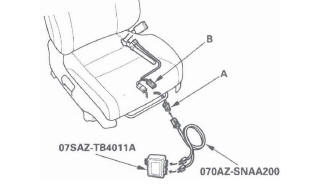
5. Connect the SRS inflator simulator (2 Ω connectors) and simulator lead K to the front passenger's seat subharness connector.
6. Reconnect the negative cable to the battery.
7. Erase the DTC memory.
8. Read the DTC (see page 24-25).
Is DTC 28-9x indicated? YES-Go to step 9.
NO-Short to ground in the front passenger's seat belt buckle tensioner; replace the front passenger's seat belt buckle.
9. Turn the ignition switch OFF. Disconnect the negative cable from the battery, and wait for 3 minutes.
10. Disconnect both seat belt tensioner 4P connectors (see step 7) and the driver's seat belt buckle tensioner 4P connector (see step 8).
11. Disconnect SRS unit connector B (28P) from the SRS unit (see step 9).
12. Disconnect the simulator lead from the front passenger's seat subharness.
13. Check resistance between the No.9 terminal of SRS unit connector B (28P) and body ground, and the No. 10 terminal and body ground. There should be an open circuit (ohmmeter reads OL) or at least 1 MΩ.
Is the resistance as specified? YES-Faulty SRS unit or poor connection at SRS unit connector B (28P) and the SRS unit. Check the connection; if the connection is OK, replace the SRS unit.
NO-Go to step 14.
14. Disconnect center floor wire harness 4P connector C554 (A) from front passenger's seat subharness 4P connector C554 (B).
15. Check resistance between the No.1 terminal of floor wire harness 4P connector C554 and body ground, and between the No.2 terminal and body ground. There should be an open circuit (ohmmeter reads OL) or at least 1 M Ω.
Is the resistance as specified? YES-Short to ground in front passenger's seat subharness; replace the front passenger's seat subharness.
NO-Short to ground in floor wire harness; replace the floor wire harness.
DTC 31-1x ("X" can be 0 thru 9 or A thru F): Open or Increased Resistance in Driver's Side Airbag Inflator
Special Tools Required
- SRS inflator simulator 07SAZ-TB4011A
- SRS simulator lead L 070AZ-SNAA300
NOTE: Before doing this troubleshooting procedure, review SRS Precautions and Procedures.
1. Erase the DTC memory.
2. Turn the ignition switch ON (II), and check that the SRS indicator comes on for about 6 seconds and then goes off.
Does the SRS indicator stay on, and is DTC 31-1x indicated? YES-Go to step 3.
NO-Intermittent failure, the system is OK at this time. Go to Troubleshooting Intermittent Failures. If another DTC is indicated, go to the DTC Troubleshooting Index.
3. Turn the ignition switch OFF. Disconnect the negative cable from the battery, and wait for 3 minutes.
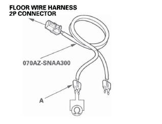
4. Disconnect the floor wire harness 2P connector (A) from the driver's side airbag (B).
5. Connect the SRS inflator simulator (2 Ω connectors) and simulator lead L to the floor wire harness.
6. Reconnect the negative cable to the battery.
7. Erase the DTC memory.
8. Read the DTC.
Is DTC 31-1x indicated? YES-Go to step 9.
NO-Open or increased resistance in the driver's side airbag inflator; replace the driver's side airbag.
9. Turn the ignition switch OFF. Disconnect the negative cable from the battery, and wait for 3 minutes.
10. Disconnect both seat belt tensioner 4P connectors (see step 7) and both seat belt buckle tensioner 4P connectors (see step 8).
11. Disconnect SRS unit connector B (28P) from the SRS unit (see step 9).
12. Disconnect the SRS inflator simulator from SRS simulator lead. Do not disconnect the simulator lead from the floor wire harness 2P connector.
13. Check resistance between the terminals of the black SRS simulator lead (A). There should be 1.0 Ω or less.
Is the resistance as specified? YES-Faulty SRS unit or poor connection at SRS unit connector B (28P) and the SRS unit. Check the connection; if the connection is OK, replace the SRS unit.
NO-Open or increased resistance in the floor wire harness; replace the floor wire harness.
READ NEXT:
 DTC 31-3x ("x" can be 0 thru 9 or A thru F):
Short to Another Wire or Decreased
Resistance in Driver's Side Airbag Inflator
DTC 31-3x ("x" can be 0 thru 9 or A thru F):
Short to Another Wire or Decreased
Resistance in Driver's Side Airbag Inflator
Special Tools Required
SRS inflator simulator 07SAZ-TB4011A
SRS simulator lead L 070AZ-SNAA300
SRS short canceller 070AZ-SAA0100
NOTE: Before doing this troubleshooting procedure, review SRS Prec
DTC 32-8x ("x" can be 0 thru 9 or A thru F):
Short to Power in Front Passenger's Side
Airbag Inflator
Special Tools Required
SRS inflator simulator 07SAZ-TB4011A
SRS simulator lead L 070AZ-SNAA300
NOTE: Before doing this troubleshooting procedure,
review SRS Precautions and Procedures.
1. Erase t
DTC 33-9x ("x" can be 0 thru 9 or A thru F):
Short to Ground in Left Side Curtain Airbag
Inflator
Special Tools Required
SRS inflator simulator 07SAZ-TB4011A
SRS simulator lead L 070AZ-SNAA300
NOTE: Before doing this troubleshooting procedure,
review SRS Precautions and Procedures.
1. Erase t
SEE MORE:
CD, DVD, and PC Card Removal/Installation
If the display will not open, use this procedure to
manually open the display and remove the CD, DVD,
and/or the PC card.
1. Remove the navigation unit from the vehicle.
2. On the bench, carefully pull the display (A) straight
out (about 1/2 inch).
3. Fold down the display as shown in the diagram
Crankshaft Installation
Special Tools Required
Driver 077 49-00 10000
Oil seal driver attachment, 96 mm 07ZAD-PNAA.100
1. Check the connecting rod bearing clearance with
plastigage.
2. Check the main bearing clearance with plastigage.
3. Install the bearing halves in the engine block and
connecting rods.
4. Apply a
