Honda CR-V: DTC 41-1x ("x" can be 0 thru 9 or A thru F): No Signal From the Left Front Impact Sensor
Specia1 Tools Required
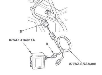
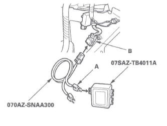
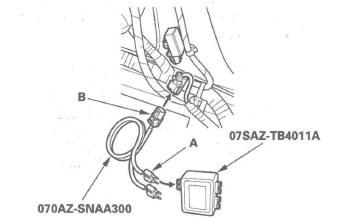
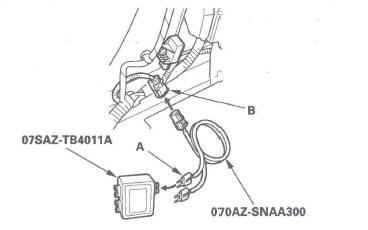
SRS inflator simulator 07SAZ-TB4011A
SRS simulator lead L 070AZ-SNAA300
NOTE: Before doing this troubleshooting procedure, review SRS Precautions and Procedures.
1. Erase the DTC memory.
2. Turn the ignition switch ON (II), and check that the SRS indicator comes on for about 6 seconds and then goes off.
Does the SRS indicator stay on, and is DTC 41-1x indicated? YES-Go to step 3.
NO-Intermittent failure, the system is OK at this time. Go to Troubleshooting Intermittent Failures. If another DTC is indicated, go to the DTC Troubleshooting Index.
3. Turn the ignition switch OFF.
4. Disconnect the negative cable from the battery, and wait for 3 minutes.
5. Check the connections between SRS unit connector A (28P) and the SRS unit, between the engine compartment wire harness 2P connector and the left front impact sensor, and at connector C503.
Are the connections OK? YES-Go to step 6.
NO-Repair the poor connections and retest. If DTC 41-1x is still present, go to step 6.
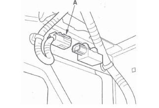
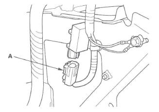
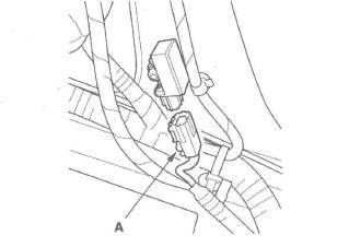
6. Disconnect the engine compartment wire harness 2P connector (A) from the left front impact sensor.
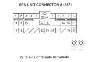
7. Disconnect SRS unit connector A (28P) from the SRS unit (see step 9).
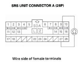
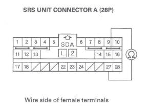
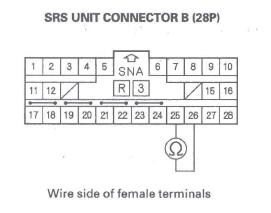
8. Check resistance between the No. 15 and No. 27 terminals of SRS unit connector A (28P). There should be an open circuit (ohmmeter reads OL) or at least 1 M Ω.
Is the resistance as specified? YES-Go to step 9.
NO-Short in the engine compartment wire harness or dashboard wire harness; replace the faulty harness.
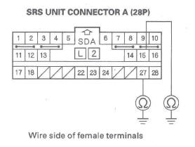
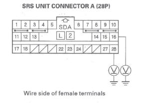
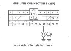
9. Check resistance between the No. 15 terminal of SRS unit connector A (28P) and body ground, and between the No. 27 terminal and body ground.
There should be an open circuit (ohmmeter reads OL) or at least 1 M Ω.
Is the resistance as specified? YES-Go to step 10.
NO-Short to ground in the dashboard wire harness or the engine compartment wire harness; replace the faulty harness.
10. Reconnect the negative cable to the battery.
11. Turn the ignition switch ON (II).
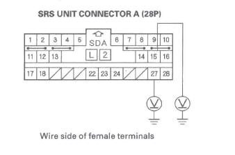
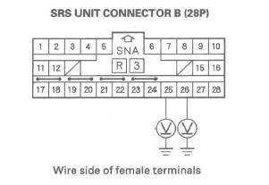
12. Check for voltage between the No. 15 terminal of SRS unit connector A (28P) and body ground, and between the No. 27 terminal and body ground.
There should be 1 V or less.
Is the voltage as specified? YES-Go to step 13.
NO-Short to power in the engine compartment wire harness or the dashboard wire harness; replace the faulty harness.
13. Turn the ignition switch OFF.
14. Connect the SRS inflator simulator (jumper connector) and the black lead (A) of simulator lead l to the engine compartment wire harness 2P connector (B).
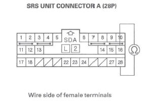
15. Check resistance between the No. 15 and No. 27 terminals of SRS unit connector A (28P). There should be 0-1.0 Ω.
Is the resistance as specified? YES-Faulty left front impact sensor or SRS unit; replace the left front impact sensor (see page 24-182). If the problem is still present, replace the SRS unit.
NO-Poor connection at C503, open in the engine compartment wire harness, or open in the dashboard wire harness. Inspect C503. If it is OK, replace the faulty harness.
DTC 42-1x ("x" can be 0 thru ,g or A thru F): No Signal From the Right Front Impact Sensor
Special Tools Required
- SRS inflator simulator 07SAZ-TB4011A
- SRS simulator lead L 070AZ-SNAA300
NOTE: Before doing this troubleshooting procedure, review SRS Precautions and Procedures.
1. Erase the DTC memory.
2. Turn the ignition switch ON (II), and check that the SRS indicator comes on for about 6 seconds and then goes off.
Does the SRS indicator stay on, and is DTC 42-1x indicated? YES-Go to step 3.
NO-Intermittent failure, the system is OK at this time. Go to Troubleshooting Intermittent Failures. If another DTC is indicated, go to the DTC Troubleshooting Index.
3. Turn the ignition switch OFF.
4. Disconnect the negative cable from the battery, and wait for 3 minutes.
5. Check the connections between SRS unit connector A (28P) and the SRS unit, between the engine compartment wire harness 2P connector and the right front impact sensor, and at connector C503.
Are the connections OK? YES-Go to step 6.
NO-Repair the poor connections and retest. If DTC 42-1x is still present, go to step 6.
6. Disconnect the engine compartment wire harness 2P connector (A) from the right front impact sensor.
7. Disconnect SRS unit connector A (28P) from the SRS unit (see step 9).
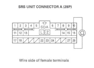
8. Check resistance between the No. 16 and No. 28 terminals of SRS unit connector A (28P). There should be an open circuit (ohmmeter reads OL) or at least 1 M Ω.
Is the resistance as specified? YES-Go to step 9.
NO-Short in the engine compartment wire harness or dashboard wire harness; replace the faulty harness.
9. Check resistance between the No. 16 terminal of SRS unit connector A (28P) and body ground, and between the No. 28 terminal and body ground.
There should be an open circuit (ohmmeter reads OL) or at least 1 M Ω.
Is the resistance as specified? YES-Go to step 10.
NO-Short to ground in the dashboard wire harness or the engine compartment wire harness; replace the faulty harness.
10. Reconnect the negative cable to the battery.
11. Turn the ignition switch ON (II).
12. Check for voltage between the No. 16 terminal of SRS unit connector A (28P) and body ground, and between the No. 28 terminal and body ground.
There should be 1 V or less.
Is the voltage as specified? YES-Go to step 13.
NO-Short to power in the engine compartment wire harness or dashboard wire harness; replace the faulty harness.
13. Turn the ignition switch OFF.
14. Connect the SRS inflator simulator (jumper connector) and the black lead (A) of simulator lead L to the engine compartment wire harness 2P connector (B).
15. Check resistance between the No. 16 and No. 28 terminals of SRS unit connector A (28P). There should be 0-1.0 Ω.
Is the resistance as specified? YES-Faulty right front impact sensor or SRS unit; replace the right front impact sensor (see page 24-182). If the problem is still present, replace the SRS unit.
NO-Poor connection at C503, open in the engine compartment wire harness, or open in the dashboard wire harness. Inspect C503 (see page 22-22). If it is OK, replace the faulty harness.
DTC 41-2x, 41-3x, 41-Bx ("x" can be 0 thru 9 or A thru F): Internal Failure of the Left Front Impact Sensor DTC 42-2x, 42-3x, 42-Bx ("x" can be 0 thru 9 or A thru F): Internal Failure of Right Front Impact Sensor
NOTE: Before doing this troubleshooting procedure, review SRS Precautions and Procedures.
1. Erase the DTC memory.
2. Turn the ignition switch ON (II), and check that the SRS indicator comes on for about 6 seconds and then goes off.
Does the SRS indicator stay on; and is DTC 41-2x, 41-3x, 41-Bx, 42-2x, 42-3x, or 42-Bx indicated? YES-Replace the left or right front impact sensor (see page 24-182). If the DTC returns, replace the SRS unit.
NO-Intermittent failure, the system is OK at this time. Go to Troubleshooting Intermittent Failures. If another DTC is indicated, go to the DTC Troubleshooting Index.
DTC 43-1x ("X" can be 0 thru 9 or A thru F): No Signal From the Left Side Impact Sensor (first)
Special Tools Required
- SRS inflator simulator 07SAZ-TB4011A
- SRS simulator lead L 070AZ-SNAA300
NOTE: Before doing this troubleshooting procedure, review SRS Precautions and Procedures.
1. Erase the DTC memory.
2. Turn the ignition switch ON (II), and wait for 10 seconds.
3. Read the DTC.
Is DTC 43-11 indicated? YES-Go to step 6.
NO-Go to step 4.
4. Read the DTC.
Is DTC 43-12 indicated? YES-Go to step 5.
NO-Intermittent failure, the system is OK at this time. Go to Troubleshooting Intermittent Failures. If DTC 43-1x except DTC 43-11 and 43-12 is indicated, faulty left side impact sensor (first); replace the left side impact sensor (first).
5. Read the DTC.
Is DTC 45-11 aiso indicated? YES-Faulty left side impact sensor (first); replace the left side impact sensor (first).
NO-Go to step 6.
6. Turn the ignition switch OFF.
7. Disconnect the negative cable from the battery, and wait for 3 minutes.
8. Disconnect both seat belt tensioner connectors (see step 7) and both seat belt buckle tensioner connectors (see step 8).
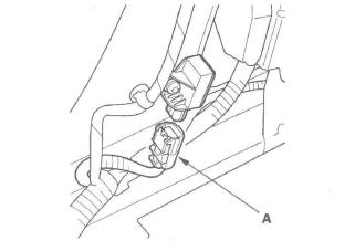
9. Disconnect the floor wire harness 4P connector (A) from the left side impact sensor (first).
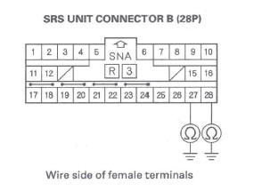
10. Disconnect SRS unit connector B (28P) from the SRS unit (see step 9).
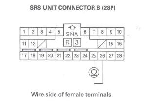
11. Check resistance between the No. 25 and No. 26 terminals of SRS unit connector B (28P). There should be an open circuit (ohmmeter reads OL) or at least 1 M Ω.
Is the resistance as specified? YES-Go to step 12.
NO-Short in the floor wire harness; replace the floor wire harness.
12. Check resistance between the No. 25 terminal of SRS unit connector B (28P) and body ground, and between the No. 26 terminal and body ground.
There should be an open circuit (ohmmeter reads OL) or at least 1 M Ω.
Is the resistance as specified? YES-Go to step 13.
NO-Short to ground in the floor wire harness; replace the floor wire harness.
13. Reconnect the negative cable to the battery.
14. Turn the ignition switch ON (II).
15. Check for voltage between the No. 25 terminal of SRS unit connector B (28P) and body ground, and between the No. 26 terminal and body ground.
There should be 1 V or less.
Is the voltage as specified? YES-Go to step 16.
NO-Short to power in the floor wire harness; replace the floor wire harness.
16. Turn the ignition switch OFF.
17. Connect the SRS inflator simulator (jumper connector) and the black lead (A) of simulator lead L to the left side impact sensor 4P connector (B).
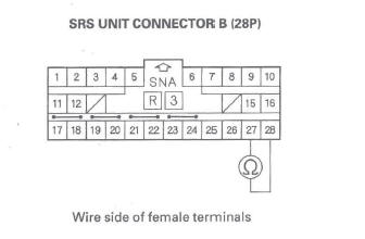
18. Check resistance between the No. 25 and No. 26 terminals of SRS unit connector B (28P). There should be 0-1.0 Ω.
Is the resistance as specified? YES-Faulty left side impact sensor (first) or SRS unit; replace the left side impact sensor (first) (see page 24-177). If the problem is still present, replace the SRS unit.
NO-Open in the floor wire harness; replace the floor wire harness.
DTC 44-1x ("X" can be 0 thru 9 or A thru F): No Signal From the Right Side Impact Sensor (first)
Special Tools Required
- SRS inflator simulator 07SAZ-TB4011A
- SRS simulator lead L 070AZ-SNAA300
NOTE: Before doing this troubleshooting procedure, review SRS Precautions and Procedures.
1. Erase the DTC memory.
2. Turn the ignition switch ON (II), and wait for 10 seconds.
3. Read the DTC.
Is DTC 44-11 indicated? YES-Go to step 5.
NO-Go to step 4.
4. Read the DTC.
Is DTC 44-12 indicated? YES-Faulty right side impact sensor (first); replace the right side impact sensor (first).
NO-Intermittent failure, the system is OK at this time. Go to Troubleshooting Intermittent Failures. If DTC 44-1x except DTC 44-11 and 44-12 is indicated, faulty right side impact sensor (first). Replace the right side impact sensor (first).
5. Turn the ignition switch OFF.
6. Disconnect the negative cable from the battery, and wait for 3 minutes.
7. Disconnect both seat belt tensioner connectors (see step 7) and both seat belt buckle tensioner connectors (see step 8).
8. Disconnect the floor wire harness 4P connector (A) from the right side impact sensor (first).
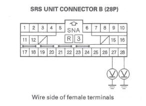
9. Disconnect SRS unit connector B (28P) from the SRS unit (see step 9).
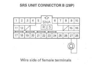
10. Check resistance between the No. 27 and No. 28 terminals of SRS unit connector B (28P). There should be an open circuit (ohmmeter reads OL) or at least 1 M Ω.
Is the resistance as specified? YES-Go to step 11.
NO-Short in the floor wire harness; replace the floor wire harness.
11. Check resistance between the No. 28 terminal of SRS unit connector B (28P) and body ground, and between the No. 27 terminal and body ground.
There should be an open circuit (ohmmeter reads OL) or at least 1 M Ω.
Is the resistance as specified? YES-Go to step 12.
NO-Short to ground in the floor wire harness; replace the floor wire harness.
12. Reconnect the negative cable to the battery.
13. Turn the ignition switch ON (II).
14. Check for voltage between the No. 28 terminal of SRS unit connector B (28P) and body ground, and between the No. 27 terminal and body ground.
There should be 1 V or less.
Is the voltage as specified? YES-Go to step 15.
NO-Short to power in the floor wire harness; replace the floor wire harness.
15. Turn the ignition switch OFF.
16. Connect the SRS inflator simulator (jumper connector) and the black lead (A) of simulator lead L to the right side impact sensor 4P connector (B).
17. Check resistance between the No. 27 and No. 28 terminals of SRS unit connector B (28P). There should be 0-1.0 Ω.
Is the resistance as specified? YES-Faulty right side impact sensor (first) or SRS unit; replace the right side impact sensor (first) (see page 24-177). If the problem is still present, replace the SRS unit.
NO-Open in the floor wire harness; replace the floor wire harness.
DTC 43-2x 43-8x, 43-8x ("x" can be 0 thru 9 or A thru F): Internal Failure of the Left Side Impact Sensor (first)
DTC 44-2x, 44-8x, 44-Bx Internal Failure of Right Side Impact Senor (first)
NOTE: Before doing this troubleshooting procedure, review SRS Precautions and Procedures.
1. Erase the DTC memory.
2. Turn the ignition switch ON (II), and check that the SRS indicator comes on for about 6 seconds and then goes off.
Does the SRS indicator stay on, and is DTC 43-2x, 43-3x, 43-Bx 44-8x or 44-Bx indicated? YES-Replace the left or right side impact sensor (first). If the DTC returns, replace the SRS unit.
NO-Intermittent failure, system is OK at this time.
Go to Troubleshooting Intermittent Failures. If another DTC is indicated, go to the DTC Troubleshooting Index.
READ NEXT:
 DTC 45-1x ("x" can be 0 thru 9 or A thru F):
No Signal From the Left Side Impact Sensor
(second)
DTC 45-1x ("x" can be 0 thru 9 or A thru F):
No Signal From the Left Side Impact Sensor
(second)
Special Tools Required
SRS inflator simulator 07SAZ-TB4011A
SRS simulator lead L 070AZ-SNAA300
NOTE: Before doing this troubleshooting procedure, review SRS Precautions and
Procedures.
1. Erase t
DTC 71-2x ("x" can be 0 thru 9 or A thru F):
Short in Driver's Seat Position Sensor
NOTE: Before doing this troubleshooting procedure,
review SRS Precautions and Procedures.
1. Erase the DTC memory.
2. Turn the ignition switch ON (II), and check that the
SRS indicator comes on for a
DTC 82-14: No Signal From the Front
Passenger's Weight Sensor (front inner side)
NOTE: Before doing this troubleshooting procedure,
review SRS Precautions and Procedures.
1. Erase the DTC memory.
2. Read the DTC.
Is DTC 82-14 indicated?
YES-Go to step 3.
NO-Intermittent failure
SEE MORE:
Road Test
1. Warm up the engine to normal operating temperature (the radiator fan comes
on).
2. Apply the parking brake, and block both rear
wheels. Start the engine, then shift to the D position
while pressing the brake pedal. Press the
accelerator pedal, and release it suddenly. The
engine should not stal
A/C Condenser Fan High Speed Circuit Troubleshooting
NOTE:
Do not use this troubleshooting procedure if the
radiator fan and/or A/C compressor is inoperative.
Refer to the symptom troubleshooting index.
Before doing symptom troubleshooting, check for
powertrain DTCs.
1. Check the No.6 (20 A) and No. 15 (7.5 A) fuses in
the under-hood fuse/rela
