Honda CR-V: DTC 11, 13, 15, 17: Wheel Sensor (Open/Short to Body Ground/Short to Power)
1. Turn the ignition switch ON (II).
2. Check for DTCs with the HDS.
Is DTC 87 indicated with DTC 11,13,15, and/or 17 at the same time? YES-Go to step 9.
NO-Go to step 3.
3. Clear the DTC with the HDS.
4. Turn the ignition switch OFF, then turn it ON (II) again.
5. Check for DTCs with the HDS.
Is DTC 11,13, 15, and/ or 17 indicated? YES-Go to step 6.
NO-Intermittent failure, the system is OK at this time. Check for loose terminals between the wheel sensor 2P connector and the VSA modulator-control unit 46P connector. Check for a loose connection at G202. Refer to intermittent failures troubleshooting.
6. Turn the ignition switch OFF.
7. Check for loose terminals between the wheel sensor 2P connector and the VSA modulator-control unit 46P connector.
Are their connections OK? YES-Go to step 8.
NO-Reconnect the connector and retest.
8. Check that the appropriate wheel sensor is properly mounted.
Is the wheel sensor installation OK? YES-Go to step 10.
NO-Reinstall the wheel sensor, and check the mounting position.
9. Turn the ignition switch OFF.
10. Disconnect the VSA modulator-control unit 46P connector.
11. Start the engine.
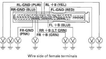
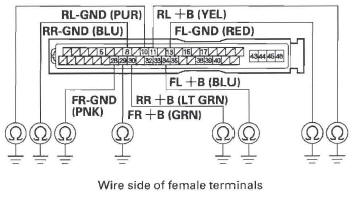
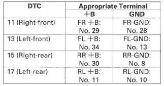
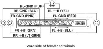
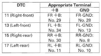
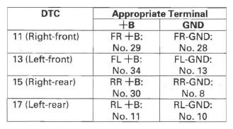
12. Measure the voltage between body ground and the appropriate wheel sensor +B and GND terminals of the VSA modulator-control unit 46P connector respectively (see table).
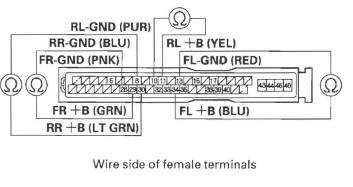
VSA MODULATOR-CONTROL UNIT 46P CONNECTOR
Is there 0.1 V or more? YES-Repair short to power in the wire between the VSA modulator-control unit and the appropriate wheel sensor.
NO-Go to step 13.
13. Turn the ignition switch OFF.
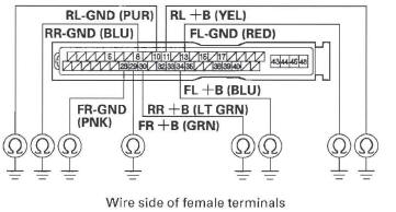
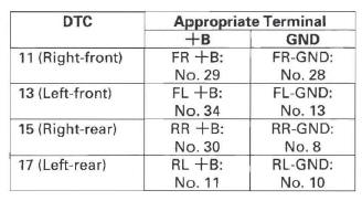
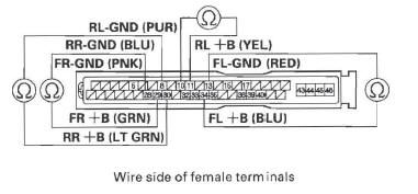
14. Check for continuity between body ground and the appropriate wheel sensor +B and GND terminals of the VSA modulator-control unit 46P connector respectively (see table).
VSA MODULATOR-CONTROL UNIT 46P CONNECTOR
Is there continuity? YES-Go to step 15.
NO-Go to step 17.
15. Disconnect the appropriate wheel sensor 2P connector.
16. Check for continuity between body ground and the appropriate wheel sensor +B and GND terminals of the VSA modulator-control unit 46P connector respectively (see table).
VSA MODULATOR-CONTROL UNIT 46P CONNECTOR
Is there continuity? YES-Repair short to body ground in the wire between the VSA modulator-control unit and the appropriate wheel sensor.
NO-Replace the appropriate wheel sensor.
17. Measure resistance between the appropriate VSA modulator-control unit 46P connector wheel sensor +B and GND terminals (see table), then measure the resistance between the same terminals and reverse the positive and negative tester probes.
VSA MODULATOR-CONTROL UNIT 46P CONNECTOR
Is the resistance infinity (Ohmmeter may read OL) in both directions? YES-Go to step 18.
NO-Go to step 20.
18. Disconnect the appropriate wheel sensor 2P connector.
19. On the sensor side, measure resistance between appropriate wheel sensor 2P connector terminals No.1 and No.2, then measure resistance between the same terminals and reverse the positive and negative tester probes.
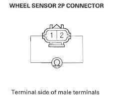
Is the resistance infinity (Ohmmeter may read OL) in both directions? YES-Replace the appropriate wheel sensor.
NO-Repair open in the wire between the appropriate wheel sensor and the VSA modulator-control unit.
20. Check for continuity between the appropriate VSA modulator-control unit 46P connector wheel sensor +B and GND terminals (see table), then check for continuity between the same terminals and reverse the positive and negative taster probes.
VSA MODULATOR-CONTROL UNIT 46P CONNECTOR
Is there continuity in both directions? YES-Go to step 21.
NO-Check for loose terminals in the VSA modulator-control unit 46P connector. Check for a loose connection at G202. If necessary, substitute a known-good VSA modulator-control unit and retest.
21. Disconnect the appropriate wheel sensor 2P connector.
22. Check for continuity between the appropriate VSA modulator-control unit 46P connector wheel sensor +B and GND terminals (see table), then check for continuity between the same terminals and reverse the positive and negative tester probes.
VSA MODULATOR-CONTROL UNIT 46P CONNECTOR
Is there continuity in both directions? YES-Repair short in the wires between the VSA modulator-control unit and the appropriate wheel sensor.
NO-Replace the appropriate wheel sensor.
READ NEXT:
 DTC 12, 14, 16, 18: Wheel Sensor (Electrical
Noise/Intermittent Interruption)
DTC 12, 14, 16, 18: Wheel Sensor (Electrical
Noise/Intermittent Interruption)
NOTE:
If the ABS and other indicators come on because of
electrical noise, the indicators will go off when you
test-drive the vehicle at 10 mph (15 km/h) or more
and noise is gone.
An incorrectl
DTC 51: Motor Locked
1. Turn the ignition switch ON (II).
2. Clear the DTC with the HDS.
3. Test-drive the vehicle. Drive the vehicle at 10 mph
(15 km/h) or more, with the engine speed at
2,500 rpm or more.
4. Check fo
DTC 86: F-CAN Communication
1. Turn the ignition switch ON (II).
2. Clear the DTC with the HDS.
3. Turn the ignition switch OFF.
4. Start the engine.
5. Wait at least 5 seconds.
6. Check for DTCs with the HDS.
Is DTC 86 in
SEE MORE:
Information Display
As an incoming call notification, you
will see the following display:
A notification that there is an
incoming call, or HFL is in use, will
appear on the navigation screen
when the audio system is on.
When there is an incoming call, or
HFL is in use, ‘‘HFL’’ will appear at
Remote Audio Controls
If equipped
Three controls for the audio system
are mounted in the steering wheel
hub. These let you control basic
functions without removing your
hand from the wheel.
The VOL button adjusts the volume
up ( ) or down (
). Press the top
or bottom of the button and hold it
until
