Honda CR-V: DTC 12, 14, 16, 18: Wheel Sensor (Electrical Noise/Intermittent Interruption)
NOTE:
- If the ABS and other indicators come on because of electrical noise, the indicators will go off when you test-drive the vehicle at 10 mph (15 km/h) or more and noise is gone.
- An incorrectly installed wheel bearing can cause one of these DTCs.
1. Turn the ignition switch OFF.
2. Check the appropriate wheel sensor and magnetic encoder on the front wheel bearing or magnetic encoder on the rear hub bearing unit.
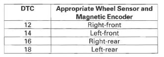
Are they installed correctly and in good condition? YES-Go to step 3.
NO-Reinstall or replace the appropriate wheel sensor, front wheel bearing, or rear hub bearing unit, and recheck by test-driving.
3. Substitute an appropriate known-good wheel sensor.
4. Turn the ignition switch ON (II).
5. Clear the DTC with the HDS.
6. Test-drive the vehicle at 10 mph (15 km /h) or more.
7. Check for DTCs with the HDS.
Is DTCs 12, 14, 16, and/ or 18 indicated? YES-Go to step 8.
NO-Replace the original wheel sensor.
8. Turn the ignition switch OFF.
9. Replace the appropriate front wheel bearing (see page 18-16), or substitute a known-good rear hub bearing unit.
10. Turn the ignition switch ON (II).
11. Clear the DTC with the HDS.
12. Test-drive the vehicle at 10 mph (15 km /h) or more.
13. Check for DTCs with the HDS.
Is DTCs 12, 14, 16, and/or 18 indicated? YES-Check for loose terminals in the VSA modulator-control unit 46P connector. Check for a loose connection at G202. If necessary, substitute a known-good VSA modulator-control unit (see page 19-97) and retest.
NO-
- Front: Troubleshooting is complete.
- Rear: Replace the original rear hub bearing unit.
DTC 25: Yaw Rate Sensor (Sensor Unit)
DTC 26: Lateral Acceleration Sensor (Sensor Unit)
1. Turn the ignition switch OFF.
2. Substitute a known-good yaw rate-lateral acceleration sensor.
3. Turn the ignition switch ON (II).
4. Clear the DTC with the HDS.
5. Test-drive the vehicle. Drive the vehicle at 19 mph (30 km/h) or more, and go a distance of 985 ft (300 m) or more.
6. Check for DTCs with the HDS.
Is DTC 25 or 26 indicated? YES-Check for loose terminals in the VSA modulator-control unit 46P connector. Check for a loose connection at G202. If necessary, substitute a known-good VSA modulator-control unit (see page 19-97) and retest.
NO-Replace the original yaw rate-lateral acceleration sensor.
DTC 27: Steering Angle Sensor (Hardware)
1. Turn the ignition switch OFF.
2. Disconnect the steering angle sensor 5P connector.
3. Disconnect the VSA modulator-control unit 46P connector.
4. Turn the ignition switch ON (II).
5. Measure the voltage between body ground and VSA modulator-control unit 46P connector terminals No.5, No. 17, No. 32, and No. 35 respectively.
VSA MODULATOR-CONTROL UNIT 46P CONNECTOR
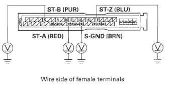
Is there 0.1 V or more? YES-Repair short to power in the wire between the VSA modulator-control unit and the steering angle sensor.
NO-Go to step 6.
6. Turn the ignition switch OFF.
7. Check for continuity between body ground and VSA modulator-control unit 46P connector terminals No.5, No. 17, and No. 32 respectively.
VSA MODULATOR-CONTROL UNIT 46P CONNECTOR
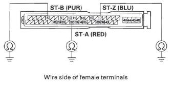
Is there continuity? YES-Repair short to body ground in the wire between the VSA modulator-control unit and the steering angle sensor.
NO-Go to step 8.
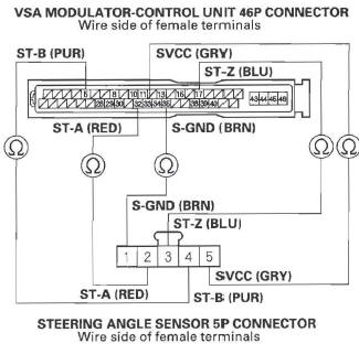
8. Check for continuity between the appropriate VSA modulator-control unit 46P connector terminals and steering angle sensor 5P connector terminals respectively (see table).
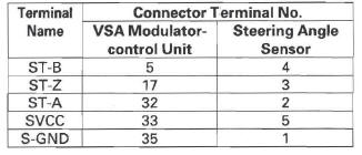
VSA MODULATOR-CONTROL UNIT 46P CONNECTOR
Wire side of female terminals
Is there continuity? YES-Go to step 9.
NO-Repair open in the wire between the VSA modulator-control unit and the steering angle sensor.
9. Substitute a known-good steering angle sensor.
10. Reconnect all connectors.
11. Turn the ignition switch ON (II).
12. Clear the DTC with the HDS.
13. Test-drive the vehicle around a number of corners.
14. Check for DTCs with the HDS.
Is DTC 27 indicated? YES-Check for loose terminals in the VSA modulator-control unit 46P connector. Check for a loose connection at G202. If necessary, substitute a known-good VSA modulator-control unit (see page 19-97), and retest.
NO-Replace the original steering angle sensor.
DTC 31, 32, 33, 34, 35, 36, 37, 38: ABS Solenoid
1. Turn the ignition switch ON (II).
2. Clear the DTC with the HDS.
3. Turn the ignition switch OFF, then turn it ON (II) again.
4. Check for DTCs with the HDS.
Is DTC 31, 32,33,34, 35, 36,37, and/ or 38 indicated? YES-Replace the VSA modulator-control unit.
NO-Intermittent failure, the system is OK at this time. Check for a loose connection at G202.
READ NEXT:
 DTC 51: Motor Locked
1. Turn the ignition switch ON (II).
2. Clear the DTC with the HDS.
3. Test-drive the vehicle. Drive the vehicle at 10 mph
(15 km/h) or more, with the engine speed at
2,500 rpm or more.
4. Check fo
DTC 86: F-CAN Communication
1. Turn the ignition switch ON (II).
2. Clear the DTC with the HDS.
3. Turn the ignition switch OFF.
4. Start the engine.
5. Wait at least 5 seconds.
6. Check for DTCs with the HDS.
Is DTC 86 in
DTC 91: VSA System
1. Check the brake system for leaks or mechanical
problems.
Is the brake system OK? (No brake fluid leakage,
no air trapped in the brake system, no brake pads
worn out.)
YES-Go to step 2.
NO-Repair
SEE MORE:
A/C Service Tips and Precautions
WARNING
Compressed air mixed with the R-134a forms a
combustible vapor.
The vapor can burn or explode causing serious
injury.
Never use compressed air to pressure test
R-134a service equipment or vehicle air
conditioning systems.
CAUTION
Air conditioning refrigerant or lubricant vapor
ca
XM radio display is blank and no station
information is displayed
1. Disconnect audio disc changer 13P connector.
2. Turn the ignition switch to ACC (I).
3. Operate the XM radio, and check the display.
Is XM information displayed? YES-Replace the audio disc changer.
NO-Go to step 4.
4. Check the No. 34 (7.5 A) fuse in the under-dash
fuse/relay box and the No.
