Honda CR-V: DTC 22-3x ("x" can be 0 thru 9 or A thru F): Short to Another Wire or Decreased Resistance in Front Passenger's Seat Belt Tensioner
Special Tools Required
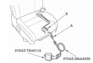
- SRS inflator simulator 07SAZ-TB4011A
- SRS simulator lead K 070AZ-SNAA200
NOTE: Before doing this troubleshooting procedure, review SRS Precautions and Procedures.
1. Erase the DTC memory.
2. Turn the ignition switch ON (II), and check that the SRS indicator comes on for about 6 seconds and then goes off.
Does the SRS indicator stay on, and is DTC 22-3x indicated? YES-Go to step 3.
NO-Intermittent failure, the system is OK at this time. Go to Troubleshooting Intermittent Failures. If another DTC is indicated, go to the DTC Troubleshooting Index.
3. Turn the ignition switch OFF. Disconnect the negative cable from the battery, and wait for 3 minutes.
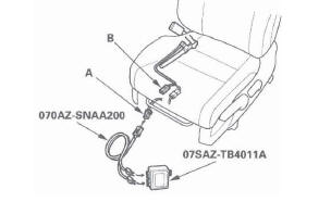
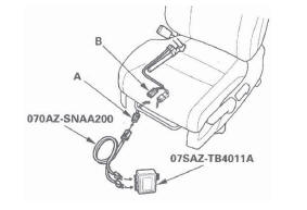
4. Disconnect the floor wire harness 4P connector (A) from the front passenger's seat belt tensioner.
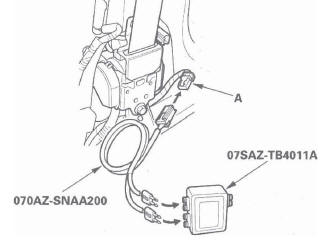
5. Connect the SRS inflator simulator (2 Ω connectors) and simulator lead K to the floor wire harness.
6. Reconnect the negative cable to the battery.
7. Erase the DTC memory.
8. Read the DTC.
Is DTC 22-3x indicated? YES-Go to step 9.
NO-Short in the front passenger's seat belt tensioner; replace the front passenger's seat belt.
9. Turn the ignition switch OFF. Disconnect the negative cable from the battery, and wait for 3 minutes.
10. Disconnect both seat belt buckle tensioner 4P connectors (see step 8) and the driver's seat belt tensioner 4P connector (see step 7).
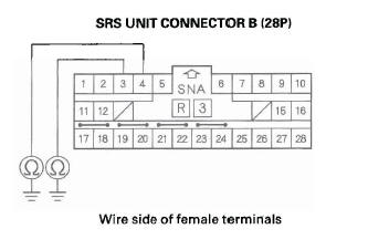
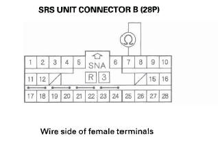
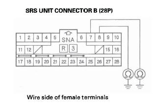
11. Disconnect SRS unit connector B(28P) from the SRS unit (see step 9).
12. Disconnect the simulator lead from the floor wire harness.
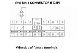
13. Check resistance between the No.3 and the NO.4 terminals of SRS unit connector B (28P). There should be an open circuit (ohmmeter reads OL) or at least 1 M Ω.
Is the resistance as specified? YES-Faulty SRS unit or poor connection at SRS unit connector B (28P) and the SRS unit. Check the connection; if the connection is OK, replace the SRS unit.
NO-Short in the floor wire harness; replace the floor wire harness.
DTC 22-8x ("x" can be 0 thru 9 or A thru F): Short to Power in Front Passenger's Seat Belt Tensioner
Special Tools Required
- SRS inflator simulator 07SAZ-TB4011A
- SRS simulator lead K 070AZ-SNAA200
NOTE: Before doing this troubleshooting procedure, review SRS Precautions and Procedures.
1. Erase the DTC memory.
2. Turn the ignition switch ON (11), and check that the SRS indicator comes on for about 6 seconds and then goes off.
Does the SRS indicator stay on, and is DTC 22-8x indicated? YES-Go to step 3.
NO-Intermittent failure, the system is OK at this time. Go to Troubleshooting Intermittent Failures. If another DTC is indicated, go to the DTC Troubleshooting Index.
3. Turn the ignition switch OFF. Disconnect the negative cable from the battery, and wait for 3 minutes.
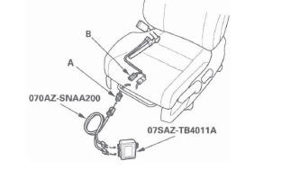
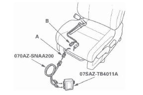
4. Disconnect the floor wire harness 4P connector (A) from the front passenger's seat belt tensioner.
5. Connect the SRS inflator simulator (2 Ω connectors) and simulator lead K to the floor wire harness.
6. Reconnect the negative cable to the battery.
7. Erase the DTC memory.
8. Read the DTC.
Is DTC 22-8x indicated? YES-Go to step 9.
NO-Short to power in the front passenger's seat belt tensioner; replace the front passenger's seat belt, 9. Turn the ignition switch OFF. Disconnect the negative cable from the battery, and wait for 3 minutes.
10. Disconnect both seat belt buckle tensioner 4P connectors (see step 8) and the driver's seat belt tensioner 4P connector (see step 7).
11. Disconnect SRS unit connector B (28P) from the SRS unit (see step 9).
12. Disconnect the simulator lead from the floor wire harness.
13. Reconnect the negative cable to the battery.
14. Turn the ignition switch ON (II).
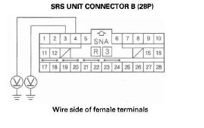
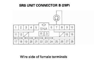
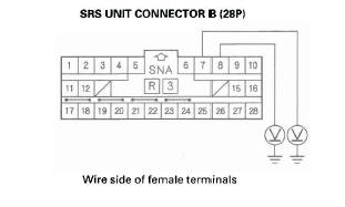
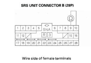
15. Check for voltage between the No.3 terminal of SRS unit connector B (28P) and body ground, and between the No.4 terminal and body ground.
There should be 0.5 V or less.
Is the voltage as specified? YES-Faulty SRS unit or poor connection at SRS unit connector B (28P) and the SRS unit. Check the connection; if the connection is OK, replace the SRS unit.
NO-Short to power in the floor wire harness; replace the floor wire harness.
DTC 22-9x ("x" can be 0 thru 9 or A thru F): Short to Ground in Front Passenger's Seat Belt Tensioner
Special Tools Required
- SRS inflator simulator 07SAZ-TB4011A
- SRS simulator lead K 070AZ-SNAA200
NOTE: Before doing this troubleshooting procedure, review SRS Precautions and Procedures.
1. Erase the DTC memory.
2. Turn the ignition switch ON (11), and check that the SRS indicator comes on for about 6 seconds and then goes off.
Does the SRS indicator stay on, and is DTC 22-9x indicated? YES-Go to step 3.
NO-Intermittent failure, the system is OK at this time. Go to Troubleshooting Intermittent Failures. If another DTC is indicated, go to the DTC Troubleshooting Index.
3. Turn the ignition switch OFF. Disconnect the negative cable from the battery, and wait for 3 minutes.
4. Disconnect the floor wire harness 4P connector (A) from the front passenger's seat belt tensioner.

5. Connect the SRS inflator simulator (2 Ω connectors) and simulator lead K to the floor wire harness.
6. Reconnect the negative cable to the battery.
7. Erase the DTC memory.
8. Read the DTC.
Is DTC 22-9x indicated? YES-Go to step 9.
NO-Short to ground in the front passenger's seat belt tensioner; replace the front passenger's seat belt.
9. Turn the ignition switch OFF. Disconnect the negative cable from the battery, and wait for 3 minutes.
10. Disconnect both seat belt buckle tensioner 4P connectors (see step 8) and the driver's seat belt tensioner 4P connector (see step 7 on page 24-24).
11. Disconnect SRS unit connector B (28P) from the SRS unit (see step 9).
12. Disconnect the simulator lead from the floor wire harness.
13. Check resistance between the No.3 terminal of SRS unit connector B (28P) and body ground, and between the No.4 terminal and body ground.
There should be an open circuit or (ohmmeter reads OL) at least 1 M Ω.
Is the resistance as specified? YES-Faulty SRS unit or poor connection at SRS unit connector B (28P) and the SRS unit. Check the connection; if the connection is OK, replace the SRS unit.
NO-Short to ground in the floor wire harness; replace the floor wire harness.
DTC 27-1x ("x" can be 0 thru 9 or A thru F): Open or Increased Resistance in Driver's Seat Belt Buckle Tensioner
Special Tools Required
- SRS inflator simulator 07SAZ-TB4011A
- SRS simulator lead K 070AZ-SNAA200
NOTE: Before doing this troubleshooting procedure, review SRS Precautions and Procedures.
1. Erase the DTC memory.
2. Turn the ignition switch ON (II), and check that the SRS indicator comes on for about 6 seconds and then goes off.
Does the SRS indicator stay on, and is DTC 27-1x indicated? YES-Go to step 3.
NO-Intermittent failure, the system is OK at this time. Go to Troubleshooting Intermittent Failures. If another DTC is indicated, go to the DTC Troubleshooting Index.
3. Turn the ignition switch OFF. Disconnect the negative cable from the battery, and wait for 3 minutes.
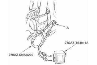
4. Disconnect the floor wire harness 4P connector (A) from the driver's seat belt buckle tensioner connector (B).
5. Connect the SRS inflator simulator (2 Ω connectors) and simulator lead K to the floor wire harness connector.
6. Reconnect the negative cable to the battery.
7. Erase the DTC memory.
8. Read the DTC.
Is DTC 27-1x indicated? YES-Go to step 9.
NO-Open or increased resistance in the driver's seat belt buckle tensioner; replace the driver's seat belt buckle.
9. Turn the ignition switch OFF. Disconnect the negative cable from the battery, and wait for 3 minutes.
10. Disconnect both seat belt tensioner 4P connectors (see step 7) and the front passenger's seat belt buckle tensioner 4P connector (see step 8).
11. Disconnect SRS unit connector B (28P) from the SRS unit (see step 9).
12. Check resistance between the No.7 and No.8 terminals of SRS unit connector B (28P). There should be 2.0-3.0 Ω.
Is the resistance as specified? YES-Faulty SRS unit or poor connection at SRS unit connector B (28P) and the SRS unit. Check the connection; if the connection is OK, replace the SRS unit.
NO-Open or increased resistance in the floor wire harness; replace the floor wire harness.
DTC 27-3x ("x" can be 0 thru 9 or A thru F): Short to Another Wire or Decreased Resistance in Driver's Seat Belt Buckle Tensioner
Special Tools Required
- SRS inflator simulator 07SAZ-TB4011A
- SRS simulator lead K 070AZ-SNAA200
NOTE: Before doing this troubleshooting procedure, review SRS Precautions and Procedures.
1. Erase the DTC memory.
2. Turn the ignition switch ON (11), and check that the SRS indicator comes on for about 6 seconds and then goes off.
Does the SRS indicator stay on, and is DTC 27-3x indicated? YES-Go to step 3.
NO-Intermittent failure, the system is OK at this time. Go to Troubleshooting Intermittent Failures. If another DTC is indicated, go to the DTC Troubleshooting Index.
3. Turn the ignition switch OFF. Disconnect the negative cable from the battery, and wait for 3 minutes.
4. Disconnect the floor wire harness 4P connector (A) from the driver's seat belt buckle tensioner connector (B).
5. Connect the SRS inflator simulator (2 Ω connectors) and simulator lead K to the floor wire harness connector.
6. Reconnect the negative cable to the battery.
7. Erase the DTC memory.
8. Read the DTC.
Is DTC 27-3x indicated? YES-Go to step 9.
NO-Short in the driver's seat belt buckle tensioner; replace the driver's seat belt buckle.
9. Turn the ignition switch OFF. Disconnect the negative cable from the battery, and wait for 3 minutes.
10. Disconnect both seat belt tensioner 4P connectors (see step 7) and the front passenger's seat belt buckle tensioner 4P connector (see step 8).
11. Disconnect SRS unit connector B (28P) from the SRS unit (see step 9).
12. Disconnect the simulator lead from the floor wire harness.
13. Check resistance between the No.7 and No.8 terminals of SRS unit connector B (28P). There should be an open circuit (ohmmeter reads OL) or at least 1 M Ω.
Is the resistance as specified? YES-Faulty SRS unit or poor connection at SRS unit connector B (28P) and the SRS unit. Check the connection; if the connection is OK, replace the SRS unit.
NO-Short in the floor wire harness; replace the floor wire harness.
DTC 27-8x ("X" can be 0 thru 9 or A thru F): Short to Power in Driver's Seat Belt Buckle Tensioner
Special Tools Required
- SRS inflator simulator 07SAZ-TB4011A
- SRS simulator lead K 070AZ-SNAA200
NOTE: Before doing this troubleshooting procedure, review SRS Precautions and Procedures.
1. Erase the DTC memory.
2. Turn the ignition switch ON (II), and check that the SRS indicator comes on for about 6 seconds and then goes off.
Does the SRS indicator stay on, and is DTC 27-8x indicated? YES-Go to step 3.
NO-Intermittent failure, the system is OK at this time. Go to Troubleshooting Intermittent Failures. If another DTC is indicated, go to the DTC Troubleshooting Index.
3. Turn the ignition switch OFF. Disconnect the negative cable from the battery, and wait for 3 minutes.
4. Disconnect the floor wire harness 4P connector (A) from the driver's seat belt buckle tensioner connector (B).
5. Connect the SRS inflator simulator (2 Ω connectors) and simulator lead K to the floor wire harness connector.
6. Reconnect the negative cable to the battery.
7. Erase the DTC memory.
8. Read the DTC.
Is DTC 27-8x indicated? YES-Go to step 9.
NO-Short to power in the driver's seat belt buckle tensioner; replace the driver's seat belt buckle.
9. Turn the ignition switch OFF. Disconnect the negative cable from the battery, and wait for 3 minutes.
10. Disconnect both seat belt tensioner 4P connectors (see step 7) and the front passenger's seat belt buckle tensioner 4P connector (see step 8).
11. Disconnect SRS unit connector B (28P) from the SRS unit (see step 9).
12. Disconnect the simulator lead from the floor wire harness.
13. Reconnect the negative cable to the battery.
14. Turn the ignition switch ON (II).
15. Check for voltage between the No.7 terminal of SRS unit connector B (28P) and body ground, and the No.8 terminal and body ground. There should be 0.5 V or less.
Is the voltage as specified? YES-Faulty SRS unit or poor connection at SRS unit connector B (28P) and the SRS unit. Check the connection; if the connection is OK, replace the SRS unit.
NO-Short to power in the floor wire harness; replace the floor wire harness.
DTC 27-9x ("x" can be 0 thru 9 or A thru F): Short to Ground in Driver's Seat Belt Buckle Tensioner
Special Tools Required
- SRS inflator simulator 07SAZ-TB4011A
- SRS simulator lead K 070AZ-SNAA200
NOTE: Before doing this troubleshooting procedure, review SRS Precautions and Procedures.
1. Erase the DTC memory.
2. Turn the ignition switch ON (II), and check that the SRS indicator comes on for about 6 seconds and then goes off.
Does the SRS indicator stay on, and is DTC 27-9x indicated? YES-Go to step 3.
NO-Intermittent failure, the system is OK at this time. Go to Troubleshooting Intermittent Failures. If another DTC is indicated, go to the DTC Troubleshooting Index.
3. Turn the ignition switch OFF. Disconnect the negative cable from the battery, and wait for 3 minutes.
4. Disconnect the floor wire harness 4P connector (A) from the driver's seat belt buckle tensioner connector (B).
5. Connect the SRS inflator simulator (2 Ω connectors) and simulator lead K to the floor wire harness connector.
6. Reconnect the negative cable to the battery.
7. Erase the DTC memory.
8. Read the DTC.
Is DTC 27 -9x indicated? YES-Go to step 9.
NO-Short to ground in the driver's seat belt buckle tensioner; replace the driver's seat belt buckle.
9. Turn the ignition switch OFF. Disconnect the negative cable from the battery, and wait for 3 minutes.
10. Disconnect both seat belt tensioner 4P connectors (see step 7) and the front passenger's seat belt buckle tensioner 4P connector (see step 8).
11. Disconnect SRS unit connector B (28P) from the SRS unit (see step 9).
12. Disconnect the simulator lead from the floor wire harness.
13. Check resistance between the No.7 terminal of SRS unit connector B (28P) and body ground, and the No.8 terminal and body ground. There should be an open circuit (ohmmeter reads OL) or at least 1 M Ω.
Is the resistance as specified? YES-Faulty SRS unit or poor connection at SRS unit connector B (28P) and the SRS unit. Check the connection; if the connection is OK, replace the SRS unit.
NO-Short to ground in the floor wire harness; replace the floor wire harness.
DTC 28-1x ("X" can be 0 thru 9 or A thru F): Open or Increased Resistance in Front Passenger's Seat Belt Buckle Tensioner
Special Tools Required
- SRS inflator simulator 07SAZ-TB4011A
- SRS simulator lead K070AZ-SNAA200
NOTE: Before doing this troubleshooting procedure, review SRS Precautions and Procedures.
1. Erase the DTC memory.
2. Turn the ignition switch ON (II), and check that the SRS indicator comes on for about 6 seconds and then goes off.
Does the SRS indicator stay on, and is DTC 28-1x indicated? YES-Go to step 3.
NO-Intermittent failure, the system is OK at this time. Go to Troubleshooting Intermittent Failures. If another DTC is indicated, go to the DTC Troubleshooting Index.
3. Turn the ignition switch OFF. Disconnect the negative cable from the battery, and wait for 3 minutes.
4. Disconnect the front passenger's seat subharness 4P connector (A) from the front passenger's seat belt buckle tensioner connector (B).
5. Connect the SRS inflator simulator (2 Ω connectors) and simulator lead K to the front passenger's seat subharness connector.
6. Recoi1nect the negative cable to the battery.
7. Erase the DIC memory.
8. Read the DTC.
Is DTC 28-1x indicated? YES-Go to step 9.
NO-Open or increased resistance in the front passenger's seat belt buckle tensioner; replace the front passenger's seat belt buckle.
9. Turn the ignition switch OFF. Disconnect the negative cable from the battery, and wait for 3 minutes.
10. Disconnect both seat belt tensioner 4P connectors (see step 7) and the driver's seat belt buckle tensioner 4P connector (see step 8).
11. Disconnect SRS unit connector B (28P) from the SRS unit (see step 9).
12. Check resistance between the No.9 and No. 10 terminals of SRS unit connector B (28P). There should be 2.0-3.0 Ω.
Is the resistance as specified? YES-Faulty SRS unit or poor connection at SRS unit connector B (28P) and the SRS unit. Check the connection; if the connection is OK, replace the SRS unit.
NO-Go to step 13.
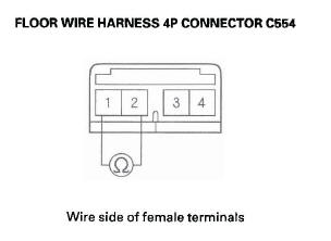
13. Disconnect floor wire harness 4P connector C554 (A) from front passenger's seat subharness 4P connector C554 (B).
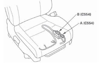
14. Check resistance between the No.1 and No.2 terminal of floor wire harness 4P connector C554.
There should be less than 1.0 Ω.
Is the resistance as specified? YES-Open or increased resistance in front passenger's seat subharness; replace the front passenger's seat subharness.
NO-Open or increased resistance in floor wire harness; replace the floor wire harness.
READ NEXT:
 DTC 28-3x ("x" can be 0 thru 9 or A thru F):
Short to Another Wire or Decreased
Resistance in Front Passenger's Seat Belt
Buckle Tensioner
DTC 28-3x ("x" can be 0 thru 9 or A thru F):
Short to Another Wire or Decreased
Resistance in Front Passenger's Seat Belt
Buckle Tensioner
Special Tools Required
SRS inflator simulator 07SAZ-TB4011A
SRS simulator lead K 070AZ-SNAA200
NOTE: Before doing this troubleshooting procedure, review SRS Precautions and
Procedures.
1. Erase t
DTC 31-3x ("x" can be 0 thru 9 or A thru F):
Short to Another Wire or Decreased
Resistance in Driver's Side Airbag Inflator
Special Tools Required
SRS inflator simulator 07SAZ-TB4011A
SRS simulator lead L 070AZ-SNAA300
SRS short canceller 070AZ-SAA0100
NOTE: Before doing this troubleshooting procedure, review SRS Prec
DTC 32-8x ("x" can be 0 thru 9 or A thru F):
Short to Power in Front Passenger's Side
Airbag Inflator
Special Tools Required
SRS inflator simulator 07SAZ-TB4011A
SRS simulator lead L 070AZ-SNAA300
NOTE: Before doing this troubleshooting procedure,
review SRS Precautions and Procedures.
1. Erase t
SEE MORE:
Moonroof
Component Location Index
MOON ROOF SWITCH
MOON ROOF CONTROL UNIT/MOTOR
Resetting the Moonroof Control Unit
Resetting the moon roof is required when any of the following have occurred:
The moonroof was moved manually while the battery was dead or
disconnected.
The moon roof motor was replac
Alternator and Regulator
Circuit Troubleshooting
1. Make sure the battery connections are good and
the battery is sufficiently charged.
2. Connect a VAT-40 (or equivalent tester), and turn
the selector switch to position 1 (starting).
3. Start the engine. Hold the engine speed at
3,000 rpm with no load until the radiator fan comes
on, then let i
