Honda CR-V: Shift Solenoid Valve
Shift Solenoid Valve Test
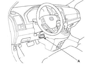
1. Connect the HDS to the DLC (A).
2. Choose Shift Solenoid A, B, C, D, and E in the Miscellaneous Test Menu on the HDS.
NOTE: If the HDS does not communicate with the PCM, troubleshoot the DLC circuit.
3. Check that shift solenoid valves A, B, C, D, and E operate with the HDS. A clicking sound should be heard.
- If a clicking sound is heard, the valves are OK.
The test is complete, disconnect the HDS.
- If no clicking sound is heard, go to step 4, and test the solenoid valves.
4. Raise the vehicle up on a lift, or apply the parking brake, block the rear wheels, and raise the front of the vehicle. Make sure it is securely supported.
5. Remove the splash shield.
6. Disconnect the shift solenoid harness connector.
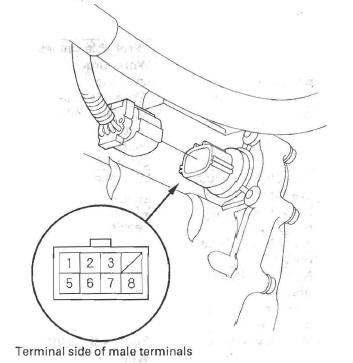
7. Measure shift solenoid valve resistance between shift solenoid harness connector terminals below and body ground:
- No. 1 terminal: Shift solenoid valve C
- No.2 terminal: Shift solenoid valve B
- No.3 terminal: Shift solenoid valve E
- No. 5 terminal: Shift solenoid valve A
- No.8 terminal: Shift solenoid valve D
Standard: 12-25 Ω
- If the resistance is within the standard, go to step 8 and check solenoid valve for clicking sound.
- If the resistance is out of standard, go to step 9 and test shift solenoid valves.
8. Connect a jumper wire from the battery positive terminal to each shift solenoid harness connector terminals individually. A clicking sound should be heard.
- If a clicking sound is heard, the valves are OK.
The test is complete, connect the connector.
- If no clicking sound is heard, go to step 9 and test shift solenoid valves.
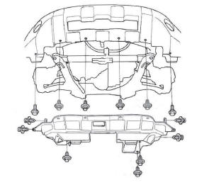
9. Remove the drain plug (A), and drain the transmission fluid (ATF).
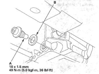
10. Reinstall the drain plug with the new sealing washer (B).
11. Make sure you have the audio system or the navigation system (if equipped) anti-theft code, and write down the audio presets.
12. Disconnect the negative terminal from the battery, then disconnect the positive terminal.
13. Remove the battery hold-down bracket, and remove the battery cover, battery, and battery tray.
14. Remove the battery base.
15. Remove the air cleaner housing and intake air duct.
16. Remove the ATF dipstick, and remove the bolts securing the ATF cooler line (A).
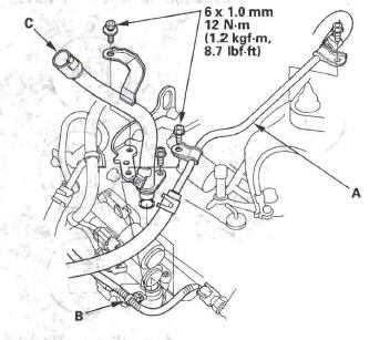
17. Remove the harness clamp (B), and remove the ATF dipstick guide tube (C).
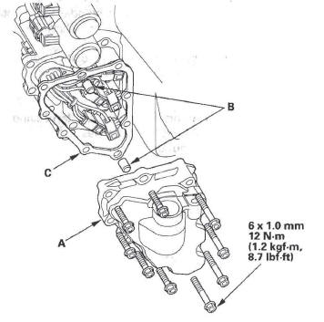
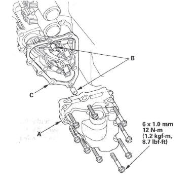
18. Remove the shift solenoid valve cover (A), dowel pins (B), and gasket (C).
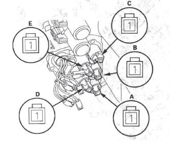
19. Disconnect the connectors from shift solenoid valve A, shift solenoid valve B, shift solenoid valve C, shift solenoid valve D, and shift solenoid valve E.
20. Measure the resistance of each shift solenoid valve between the connector terminals and body ground:
Standard: 12-25 Ω
- If the resistance is out of standard; go to step 23 and replace shift solenoid valve.
- If the resistance is within the standard, go to step 21 and check solenoid valve for a clicking sound.
21. Connect a jumper wire from the positive battery terminal to each solenoid valve terminal individually.
- If a clicking sound is heard, go to step 22 and replace the shift solenoid harness.
- If no clicking sound is heard, go to step 23 and replace shift solenoid valve.
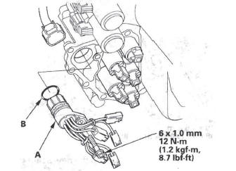
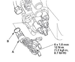
22. Remove the shift solenoid harness connector (A), and replace it. Install a new O-ring (B) on the shift solenoid harness connector, and install the connector in the transmission housing, then go to step 28.
23. Remove the mounting bolts, then remove the solenoid valves.
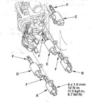
24. Install new O-rings (two O-rings per solenoid valve) (F) on the reused solenoid valves.
NOTE: A new solenoid valve comes with new O-rings. If you install a new solenoid valve, use the O-rings provided on it.
25. Install shift solenoid valve C (brown connector), shift solenoid valve D (black connector), and shift solenoid valve E (black connector) by holding the shift solenoid valve body; make sure the mounting bracket contacts the servo body.
NOTE: Do not hold the solenoid valve by the connector when installing the solenoid valve. Be sure to hold the solenoid valve body.
26. Install shift solenoid valve A (brown connector) by holding the shift solenoid valve body; make sure the mounting bracket contacts the bracket of shift solenoid valve D.
NOTE: Do not install shift solenoid valve A before installing shift solenoid valve D. If shift solenoid valve A is installed before installing shift solenoid valve D, it may damage the hydraulic control system.
27. Install shift solenoid valve B (brown connector) by holding the shift solenoid valve body; make sure the mounting bracket contacts the bracket of shift solenoid valve E.
NOTE: Do not install shift solenoid valve B before installing shift solenoid valve E. If shift solenoid valve B is installed before installing shift solenoid valve E, it may damage the hydraulic control system.
28. Connect the harness terminals to the solenoids:
- RED wire connector to shift solenoid valve E.
- GRN wire connector to shift solenoid valve C.
- ORN wire connector to shift solenoid valve B.
- BLU wire connector to shift solenoid valve A.
- VEL, WHT, WHT wire connector to shift solenoid valve D.
29. Install the shift solenoid valve cover, dowel pins, and a new gasket.
30. Install the new O-ring on the ATF dipstick guide tube, and install the guide tube then secure it with the bolts.
31. Check the connector for rust, dirt, or oil, then connect the connector securely. Install the harness clamp in its clamp bracket on the ATF dipstick guide tube.
32. Secure the ATF cooler line with the bolts.
33. Refill the transmission with ATF (see step 5).
34. Install the intake air duct and air cleaner housing.
35. Install the battery base.
36. Install the battery tray, battery, battery cover, and battery hold-down bracket, then connect battery terminals.
37. Install the splash shield.
38. Enter the audio system or the navigation system (if equipped) anti-theft code, then enter the audio presets, and set the clock.
Shift Solenoid Valve and Shift Solenoid Wire Harness Replacement
1. Make sure you have the audio system or the navigation system (if equipped) anti-theft code, and write down the audio presets.
2. Raise the vehicle on a lift, or apply the parking brake, block the rear wheels, and raise the front of the vehicle. Make sure it is securely supported.
3. Remove the splash shield.
4. Remove the drain plug (A), and drain the transmission fluid (ATF).
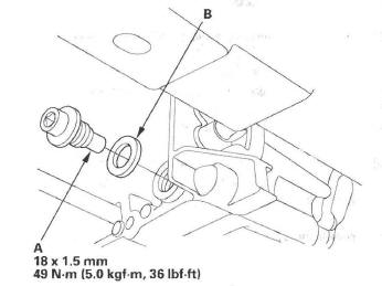
5. Reinstall the drain plug with the new sealing washer (B).
6. Disconnect the negative terminal from the battery, then disconnect the positive terminal.
7. Remove the battery hold-down bracket, and remove the battery cover, battery, and battery tray.
8. Remove the battery base.
9. Remove the air cleaner housing and intake air duct.
10. Remove the ATF dipstick, and remove the bolts securing the ATF cooler line (A).
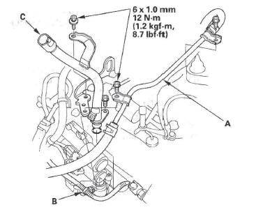
11. Remove the ha mess clamp (B), and remove the ATF dipstick guide tube (C).
12. Remove the shift solenoid valve cover (A), dowel pins (B), and gasket (C).
13. Disconnect the shift solenoid valve connectors.
- If replacing shift solenoid valve(s), go to step 14.
- If replacing the shift solenoid harness, remove the shift solenoid harness connector (A), and replace it. Install a new O-ring (B) on the shift solenoid harness connector, and install the connector in the transmission housing, then go to step 19.
14. Remove the mounting bolts, then remove the solenoid valves.
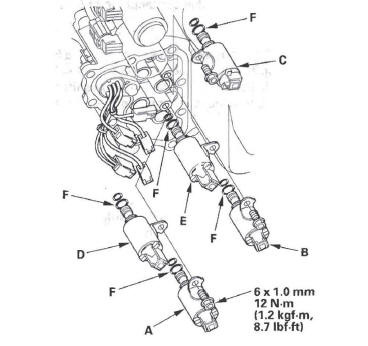
15. Install new O-rings (two O-rings per solenoid valve) (F) on the reused solenoid valves.
NOTE: A new solenoid valve comes with new O-rings. If you install a new solenoid valve, use the O-rings provided on it.
16. Install shift solenoid valve C (brown connector), shift solenoid valve D (black connector), and shift solenoid valve E (black connector) by holding the shift solenoid valve body; make sure the mounting bracket contacts the servo body.
NOTE: Do not hold the solenoid valve by the connector when installing the solenoid valve. Be sure to hold the solenoid valve body.
17. Install shift solenoid valve A (brown connector) by holding the shift solenoid valve body; make sure the mounting bracket contacts the bracket of shift solenoid valve D.
NOTE: Do not install shift solenoid valve A before installing shift solenoid valve D. If shift solenoid valve A is installed before installing shift solenoid valve D, it may damage the hydraulic control system.
18. Install shift solenoid valve B (brown connector) by holding the shift solenoid valve body; make sure the mounting bracket contacts the bracket of shift solenoid valve E.
NOTE: Do not install shift solenoid valve B before installing shift solenoid valve E. If shift solenoid valve B is installed before installing shift solenoid valve E, it may damage the hydraulic control system.
19. Connect the harness terminals to the solenoids:
- RED wire connector to shift solenoid valve E.
- GRN wire connector to shift solenoid valve C.
- ORN wire connector to shift solenoid valve B.
- BLU wire connector to shift solenoid valve A.
- VEL, WHT, WHT wire connector to shift solenoid valve D.
20. Install the shift solenoid valve cover, dowel pins, and a new gasket.
21. Install the new O-ring on the ATF dipstick guide tube, and install the guide tube then secure it with the bolts.
22. Check the connector for rust, dirt, or oil, then connect the connector securely. Install the harness clamp in its clamp bracket on the ATF dipstick guide tube.
23. Secure the ATF cooler line with the bolts.
24. Refill the transmission with ATF (see step 5 on page 14-239).
25. Install the intake air duct and air cleaner housing.
26. Install the battery base.
27. Install the battery tray, battery, battery cover, and battery hold-down bracket, then connect battery terminals.
28. Install the splash shield.
29. Enter the audio system or the navigation system (if equipped) anti-theft code, then enter the audio presets, and set the clock.
READ NEXT:
 A/T Clutch Pressure Control Solenoid Valve
A/T Clutch Pressure Control Solenoid Valve A Test
1. Connect the HDS to the DLC (A).
2. Choose Clutch Pressure Control (Linear) Solenoid A
in the Miscellaneous Test Menu on the HDS.
NOTE: If the HDS
ATF Temperature Sensor
ATF Temperature Sensor Test/Replacement
1. Raise the vehicle on a lift, or apply the parking
brake, block the rear wheels, and raise the front of
the vehicle. Make sure it is securely supported.
2. R
ATF Level Check
NOTE: Keep all foreign particles out of the transmission.
1. Park the vehicle on the level ground.
2. Warm up the engine to normal operating
temperature (the radiator fan comes on), and turn
the engi
SEE MORE:
Brake Fluid
Check the fluid level in the brake
fluid reservoir monthly.
Replace the brake fluid according to
the maintenance messages shown on
the information display.
Always use Honda Heavy Duty
Brake Fluid DOT 3. If it is not
available, you should use only DOT 3
or DOT 4 fluid, from a sealed
c
Operating the XM Radio
To listen to XM Radio, turn the
ignition switch to the ACCESSORY
(I) or the ON (II) position. Push the
power/volume knob to turn on the
audio system, and press the CD/XM
button. Adjust the volume by turning
the knob. The last channel you
listened to will show in the display.
You can a
