Honda CR-V: A/T Clutch Pressure Control Solenoid Valve
A/T Clutch Pressure Control Solenoid Valve A Test
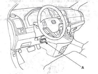
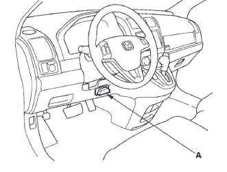
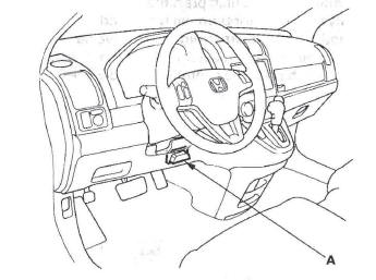
1. Connect the HDS to the DLC (A).
2. Choose Clutch Pressure Control (Linear) Solenoid A in the Miscellaneous Test Menu on the HDS.
NOTE: If the HDS does not communicate with, the PCM, troubleshoot the DLC circuit.
3. Test A/T clutch pressure control solenoid valve A with the HDS.
- If the valve tests OK, the test is complete.
Disconnect the HDS.
- If the valve does not test OK, follow the instructions on the HDS.
- If the valve does not test OK, and the HDS does not determine the cause, go to step 4.
4. Remove the air cleaner housing and intake air duct.
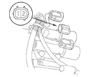
5. Disconnect the A/T clutch pressure control solenoid valve A connector.
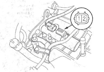
6. Measure the A/T clutch pressure control solenoid valve A resistance at the connector terminals.
Standard: 3-10 Ω
- If the resistance is out of standard, replace A/T clutch pressure control solenoid valve A.
- If the resistance is within the standard, go to step 7.
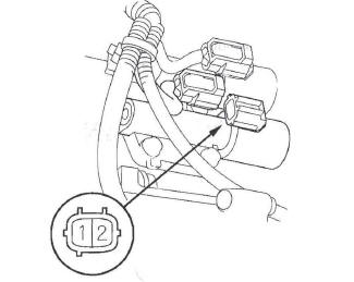
7. Connect a jumper wire from the negative battery terminal to the solenoid valve A connector terminal No.2, and connect another jumper wire from the positive battery terminal to the connector terminal No.1.
- If a clicking sound is heard, the valve is OK.
Reconnect the connector, and install all removed parts.
- If no clicking sound is heard, go to step 8.
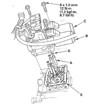
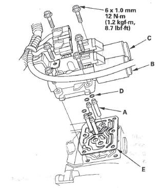
8. Remove the mounting bolts and A/T clutch pressure control solenoid valve A.
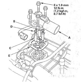
9. Remove the ATF pipe (B), ATF joint pipes (C), O-rings (D), and gasket (E).
10. Check the fluid passage of the solenoid valve for contamination.
11. Connect a jumper wire from the negative battery terminal to A/T clutch pressure control solenoid valve A connector terminal No.2, and connect another jumper wire from the positive battery terminal to the connector terminal No.1. Make sure A/T clutch pressure control solenoid valve A moves.
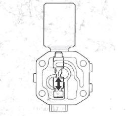
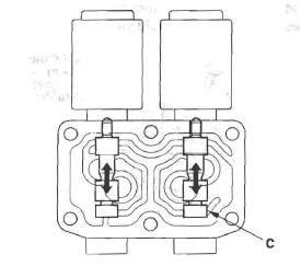
12. Disconnect one of the jumper wires and check valve movement at the fluid passage in valve body mounting surface. If the valve binds or moves sluggishly, or if the solenoid valve does not operate, replace A/T clutch pressure control solenoid valve A.
13. Clean the mounting surface and fluid passage of the solenoid valve body and transmission housing.
14. Install the new gasket on the transmission housing, and install the ATF pipe and ATF joint pipes. Install the new O-rings over the ATF joint pipes.
15. Install A/T clutch pressure control solenoid valve A.
16. Check the connector for rust, dirt, or oil, clean or repair if necessary, then connect the connector securely.
17. Install the intake air duct and air cleaner housing.
A/T Clutch Pressure Control Solenoid Valve A Replacement
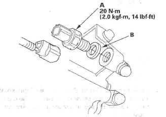
1. Remove the air cleaner housing and intake air duct.
2. Disconnect the A/T clutch pressure control solenoid valve A connector.
3. Remove the mounting bolts and A/T clutch pressure control solenoid valve A.
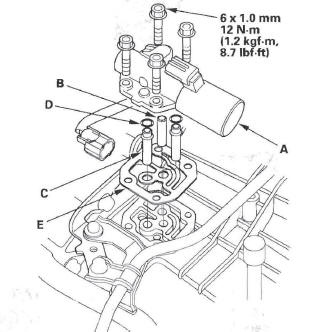
4. Remove the ATF pipe (B), ATF joint pipes (C), O-rings (D), and gasket (E).
5. Clean the mounting surface and fluid passage of the solenoid valve body and transmission housing.
6. Install the new gasket on the transmission housing, and install the ATF pipe and ATF joint pipes. Install the new O-rings over the ATF joint pipes.
7. Install A/T clutch pressure control solenoid valve A.
8. Check the connector for rust, dirt, or oil, then connect the connector securely.
9. Install the intake air duct and air cleaner housing.
A/T Clutch Pressure Control Solenoid Valve B Test
1. Connect the HDS to the DLC (A).
2. Choose Clutch Pressure Control (Linear) Solenoid B in the Miscellaneous Test Menu on the HDS.
NOTE: If the HDS does not communicate with the PCM, troubleshoot the DLC circuit.
3. Test A/T clutch pressure control solenoid valve B with the HDS.
- If the valve tests OK, the test is complete.
Disconnect the HDS.
- If the valve does not test OK, follow the instructions on the HDS.
- If the valve does not test OK, and the HDS does not determine the cause, go to step 4.
4. Raise the vehicle on a lift, or apply the parking brake, block the rear wheels, and raise the front of the vehicle. Make sure it is securely supported.
5. Remove the splash shield.
6. Disconnect the A/T clutch pressure control solenoid valve B connector.
7. Measure the A/T clutch pressure control solenoid valve B resistance at the connector terminals.
Standard: 3-10 Ω
- If the resistance is out of standard, replace A/T clutch pressure control solenoid valve B.
- If the resistance is within the standard, go to step 8.
8. Connect a jumper wire from the negative battery terminal to the solenoid valve B connector terminal No.2, and connect another jumper wire from the positive battery terminal to the connector terminal No. 1.
- If a clicking sound is heard, the valve is OK.
Reconnect the connector, and install the splash shield.
- If no clicking sound is heard, go to step 9.
9. Disconnect the connector from A/T clutch pressure control solenoid valve C.

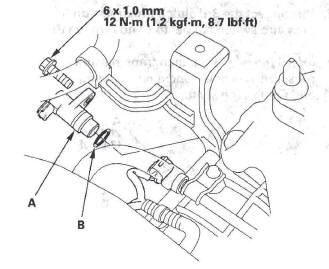
10. Remove A/T clutch pressure control solenoid valve B and C.
11. Remove the ATF joint pipes (A), O-rings (D), and gasket (E).
12. Check the fluid passage of the solenoid valve for contamination.
13. Connect a jumper wire from the negative battery terminal to A/T clutch pressure control solenoid valve B connector terminal No.2, and connect another jumper wire from the positive battery terminal to the, connector terminal No. 1, Make sure A/T clutch pressure control solenoid valve B moves.
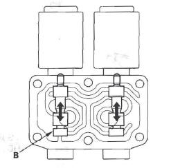
14. Disconnect one of the jumper wires and check valve movement at the fluid passage in valve body mounting surface. If the valve binds or moves sluggishly, or if the solenoid valve does not operate, replace A/T clutch pressure control solenoid valve B and C.
15. Clean the mounting surface and fluid passage of the solenoid valve body and transmission housing.
16. Install the new gasket on the transmission housing, and install the ATF joint pipes.
17. Install the new O-rings over the ATF joint pipes.
18. Install A/T clutch pressure control solenoid valve B and C.
19. Check the connectors for rust, dirt, or oil, clean or repair if necessary, then connect the connectors securely.
20. Install the splash shield.
A/T Clutch Pressure Control Solenoid Valve C Test
1. Connect the HDS to the DLC (A).
2. Choose Clutch Pressure Control (Linear) Solenoid C in the Miscellaneous Test Menu on the HDS.
NOTE: If the HDS does not communicate with the PCM, troubleshoot the DLC circuit.
3. Test A/T clutch pressure control solenoid valve C with the HDS.
- If the valve tests OK, the test is complete.
Disconnect the HDS.
- If the valve does not test OK, follow the instructions on the HDS.
- If the valve does not test OK, and the HDS does ' not determine the cause, go to step 4.
4. Raise the vehicle on a lift, or apply the parking brake, block the rear wheels, and raise the front of the vehicle. Make sure it is securely supported.
5. Remove the splash shield.
6. Disconnect the A/T clutch pressure control solenoid valve C connector.
7. Measure the A/T clutch pressure control solenoid valve C resistance at the connector terminals.
Standard: 3-10 Ω
- If the resistance is out of standard, replace A/T clutch pressure control solenoid valve C.
- If the resistance is within the standard, go to step 8.
8. Connect a jumper wire from the negative battery terminal to the solenoid valve C connector terminal No.2, and connect another jumper wire from the positive battery terminal to the connector terminal No.1.
- If a clicking sound is heard, the valve is OK.
Reconnect the connector, and install the splash shield.
- If no clicking sound is heard, go to step 9.
9. Disconnect the connector from A/T clutch pressure control solenoid valve B.
10. Remove A/T clutch pressure control solenoid valve B and C.
11. Remove the ATF joint pipes (A), O-rings (D), and gasket (E).
12. Check the fluid passage of the solenoid valve for contamination.
13. Connect a jumper wire from the negative battery terminal to A/T clutch pressure control solenoid valve C connector terminal. No.2, and connect another jumper wire from the positive battery terminal to the connector terminal No.1, Make sure A/T clutch pressure control solenoid valve C moves.
14. Disconnect one of the jumper wires and check valve movement at the fluid passage in valve body mounting surface. If the valve binds or moves sluggishly, or if the solenoid valve does not operate, replace A/T clutch pressure control solenoid valve B and C.
15. Clean the mounting surface and fluid passage of the solenoid valve body and transmission housing.
16. Install the new gasket on the transmission housing, and install the ATF joint pipes.
17. Install the new O-rings over the ATF joint pipes.
18. Install A/T clutch pressure control solenoid valve B and C.
19. Check the connectors for rust, dirt, or oil, clean or repair if necessary, then connect the connectors securely.
20. Install the splash shield.
A/T Clutch Pressure Control Solenoid Valve B and C Replacement
1. Raise the vehicle on a lift, or apply the parking brake, block the rear wheels, and raise the front of the vehicle. Make sure it is securely supported.
2. Remove the splash shield.
3. Disconnect the connectors from A/T clutch pressure control solenoid valve B and C.
4. Remove A/T clutch pressure control solenoid valve B and C.
5. Remove the ATF joint pipes (A), O-rings (D), and gasket (E).
6. Clean the mounting surface and fluid passage of the solenoid valve body and transmission housing.
7. Install the new gasket on the transmission housing, and install the ATF joint pipes.
8. Install the new O-rings over the ATF joint pipes.
9. Install A/T clutch pressure control solenoid valve B and C.
10. Check the connectors for rust, dirt, or oil, then connect the connectors securely.
11. Install the splash shield.
Input Shaft (Mainshaft) Speed Sensor Replacement
1. Remove the air cleaner housing and intake air duct.
2. Disconnect the input shaft (mainshaft) speed sensor connector, and remove the input shaft (mainshaft) speed sensor (A).
3. Install the new O-ring (B) on the new input shaft (mainshaft) speed sensor, then install the input shaft (mainshaft) speed sensor in the transmission housing.
4. Check the connector for rust, dirt, or oil, then connect the connector securely.
5. Install the intake air duct and air cleaner housing.
Output Shaft (Countershaft) Speed Sensor Replacement
1. Remove the air cleaner housing and intake air duct.
2. Disconnect the output shaft (countershaft) speed sensor connector, and remove the output shaft (countershaft) speed sensor (A) and sensor washer (B).
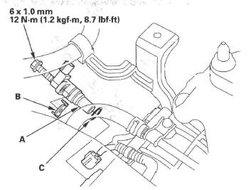
3. Install the new O-ring (C) on the new output shaft (countershaft) speed sensor, then install the output shaft (countershaft) speed sensor and sensor washer in the transmission housing.
4. Check the connector for rust, dirt, or oil, then connect the connector securely.
5. Install the intake air duct and air cleaner housing.
2nd Clutch Transmission Fluid Pressure Switch Replacement
1. Remove the air cleaner housing and intake air duct.
2. Disconnect the 2nd clutch transmission fluid pressure switch connector, and remove the switch.
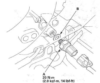
3. Install the new 2nd clutch transmission fluid pressure switch (A) and a new sealing washer (B), and tighten the switch.
4. Make sure there is no water, oil, dust, or foreign particles inside the connector.
5. Connect the connector securely.
6. Install the intake air duct and air cleaner housing.
3rd Clutch Transmission Fluid Pressure Switch Replacement
1. Raise the vehicle up on a lift, or apply the parking brake, block the rear wheels, and raise the front of the vehicle. Make sure it is securely supported.
2. Remove the splash shield.
3. Disconnect the 3rd clutch transmission fluid pressure switch connector, and remove the switch.
4. Install the new 3rd clutch transmission fluid pressure switch (A) and a new sealing washer (B), and tighten the switch.
5. Make sure there is no water, oil, dust, or foreign particles inside the connector.
6. Connect the connector securely.
7. Install the splash shield.
READ NEXT:
 ATF Temperature Sensor
ATF Temperature Sensor Test/Replacement
1. Raise the vehicle on a lift, or apply the parking
brake, block the rear wheels, and raise the front of
the vehicle. Make sure it is securely supported.
2. R
ATF Level Check
NOTE: Keep all foreign particles out of the transmission.
1. Park the vehicle on the level ground.
2. Warm up the engine to normal operating
temperature (the radiator fan comes on), and turn
the engi
ATF Replacement
NOTE: Keep all foreign particles out of the transmission.
1. Park the vehicle on the level ground.
2. Warm up the engine to normal operating
temperature (the radiator fan comes on), and turn
the eng
SEE MORE:
Torque Converter Housing
Mainshaft Bearing and Oil Seal
Replacement
Special Tools Required
Adjustable bearing puller, 25-40 mm
07736-A01000B or 07736-A01000A
Attachment, 62 x 68 mm 07746-0010500
Attachment, 72 x 75 mm 07746-0010600
Driver 07749-0010000
1. Remove the mainshaft bearing and oil seal using
the adjustabl
Floor Mats
The floor mats that came with your
vehicle hook over the floor mat
anchors. This keeps the floor mats
from sliding forward, possibly
interfering with the pedals, or
backwards, making the front
passenger’s weight sensors
ineffective.
If you remove a floor mat, make sure
to re-anc
