Honda CR-V: Hydraulic Controls
Valve Bodies
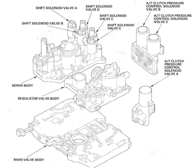
The valve body includes the main valve body, the regulator valve body, and the servo body. The ATF pump is driven by splines on the left end of the torque converter which is attached to the engine. Fluid flows through the regulator valve to maintain specified pressure through the main valve body to the manual valve, directing pressure to the shift valves and to each of the clutches via the solenoid valves. The shift solenoid valves A, B, C, D, and E are bolted on the servo body. The A/T clutch pressure control solenoid valves A, B, and C are mounted on the outside of the transmission housing.
Main Valve Body
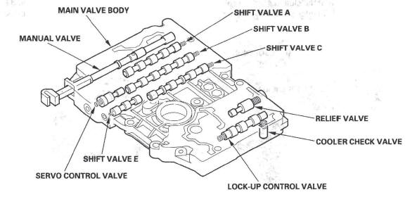
The main valve body contains the manual valve, the shift valves A, B, C, and E, the relief valve, the lock-up control valve, the cooler check valve, the servo control valve, and the ATF pump gears. The primary function of the main valve body is to switch fluid pressure on and off and to control hydraulic pressure going to the hydraulic control system.
Regulator Valve Body
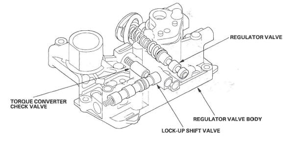
The regulator valve body contains the regulator valve, the torque converter check valve, the lock-up shift valve, and the 1st and 3rd accumulators.
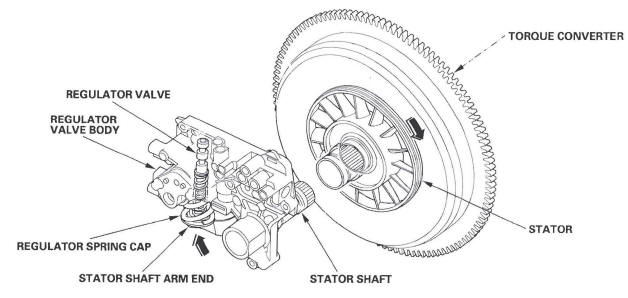
Regulator Valve
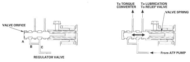
The regulator valve maintains a constant hydraulic pressure from the ATF pump to the hydraulic control system, while also furnishing fluid to the lubrication system and torque converter. Fluid from the ATF pump flows through B and C.
Fluid entering from B flows through the valve orifice to the A cavity. This pressure of the A cavity pushes the regulator valve to the right side, and this movement of the regulator valve uncovers the fluid port to the torque converter and the relief valve. The fluid flows out to the torque converter and the relief valve, and the regulator valve returns under spring force. According to the level of the hydraulic pressure through B, the position of the regulator valve changes, and the amount of fluid from C through torque converter also changes. This operation is continued, maintaining the line pressure.
Increases in hydraulic pressure according to torque are performed by the regulator valve using stator torque reaction.
The stator shaft is splined with the stator in the torque converter, and its arm end contacts the regulator spring cap.
When the vehicle is accelerating or climbing (torque converter range), stator torque reaction acts on the stator shaft, and the stator arm pushes the regulator spring cap in the direction of the arrow in proportion to the reaction. The stator reaction spring compresses, and the regulator valve moves to increase the line pressure which is regulated by the regulator valve. The line pressure reaches its maximum when the stator torque reaction reaches its maximum.
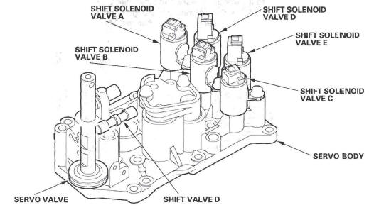
Servo Body
The servo body contains the servo valve, the shift valve D, accumulators for 2nd, 4th, and 5th, and shift solenoid valves for A, B, C, D, and E.
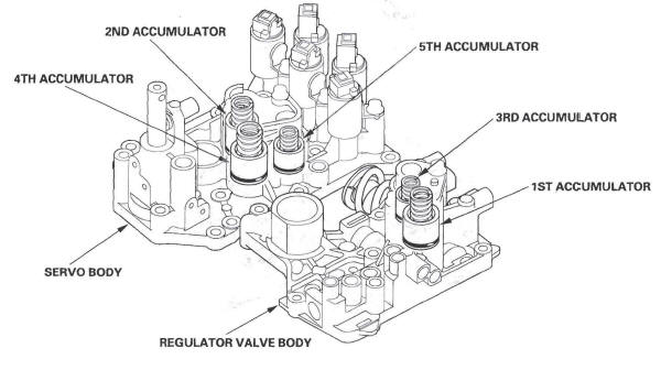
Accumulator
The accumulators are located in the regulator valve body and the servo body. The regulator valve body contains the 1st and 3rd accumulators, and the servo body contains the 2nd, 4th, and 5th accumulators.
READ NEXT:
 Hydraulic Flow
Distribution of Hydraulic Pressure
As the engine turns, the ATF pump starts to operate. Automatic transmission
fluid (ATF) is drawn through the ATF
strainer (filter) and discharged into the hydraulic
Lock-up System
The lock-up mechanism of the torque converter clutch operates in D position
(2nd, 3rd, 4th, and 5th), and in D position
D3 driving mode (2nd and 3rd). The pressurized fluid is drained from the back o
SEE MORE:
Headliner Removal/Installation
SRS components are located in this area. Review the SRS component locations
and the precautions and procedures before
doing repairs or service.
NOTE:
Put on gloves to protect your hands.
Use the appropriate tool from the KTC trim tool set to
avoid damage when prying components.
Take care not t
DTC P1683: Throttle Valve Default Position
Spring Performance Problem
CAUTION
Do not insert your fingers into the installed throttle
body when you turn the ignition switch ON (II) or
while the ignition switch is ON (II). If you do, you
will seriously injure your fingers if the throttle valve
is activated.
NOTE: Before you troubleshoot, record all freeze data and any o
