Honda CR-V: General Operation
The automatic transmission is a combination of a 3-element torque converter and triple-shaft electronically controlled unit which provides 5 speeds forward and 1 reverse. The entire unit is positioned in line with the engine.
Torque Converter, Gears, and Clutches
The torque converter consists of a pump, turbine, and stator assembly in a single unit. The converter housing (pump) is connected to the engine crankshaft and turns as the engine turns. Around the outside of the torque converter is a ring gear which meshes with the starter pinion when the engine is being started. The entire torque converter assembly serves as a flywheel while transmitting power to the transmission mainshaft, the transmission has three parallel shafts; the mainshaft, the countershaft, and the secondary shaft. The mainshaft is in line with the engine crankshaft, and includes the 4th and 5th clutches, and gears for 5th, 4th, reverse, and idler. The mainshaft reverse gear is integral with the mainshaft 4th gear. The countershaft includes the gears for 1st, 2nd, 3rd, 4th, 5th, reverse, park, and the final drive. The final drive gear is integral with the countershaft. The countershaft 4th gear and the countershaft reverse gear can be locked to the countershaft providing 4th or reverse gear, depending on which way the selector is moved.
The secondary shaft includes the 1st, 2nd, and 3rd clutches, and gears for 1st, 2nd, 3rd, and idler. The idler shaft is located between the mainshaft and secondary shaft, and the idler gear transmits power between the mainshaft and the secondary shaft. The gears on the mainshaft and the secondary shaft are in constant mesh with those on the countershaft. When certain combinations of gears in the transmission are engaged by the clutches, power is transmitted through the mainshaft, then to the secondary shaft to the countershaft or through the mainshaft to the countershaft to provide drive.
Electronic Control
The electronic control system consists of the powertrain control module (PCM), sensors, and solenoid valves. Shifting and lock-up are electronically controlled for comfortable driving under all conditions. The PCM is located under the hood next to the battery.
Hydraulic Control
The valve bodies include the main valve body, the regulator valve body, and the servo body. They are bolted to the torque converter housing. The main valve body contains the manual valve, the shift valves A, B, C, and E, the relief valve, the lock-up control valve, the cooler check valve, the servo control valve, and the ATF pump gears. The regulator valve body contains the regulator valve, the torque converter check valve, lock-up shift valve, and the 1st and 3rd accumulators. The servo body contains the servo valve, the shift valve D, accumulators for 2nd, 4th, and 5th, and shift solenoid valves for A, B, C, D, and E. Fluid from the regulator passes through the manual valve to the various control valves. The 1st, 3rd, 5th clutches receive fluid from their respective feed pipes, and the 2nd and the 4th clutches receive fluid from the internal hydraulic circuit.
Shift Control Mechanism
The PCM controls shift solenoid valves A, B, C, D, and E, and the A/T clutch pressure control solenoid valves A, B, and C, while receiving input signals from various sensors and switches located throughout the engine and transmission.
The shift solenoid valves shift the positions of the shift valves to switch the port leading hydraulic pressure to the clutch. The A/T clutch pressure control solenoid valves A, B, and C regulate their respective pressure, and pressurize to the clutches to engage it and its corresponding gear. The pressures of the A/T clutch pressure control solenoid valves also apply to the shift valves to switch the port.
Lock-up Mechanism
The lock-up mechanism operates in the D position (2nd, 3rd, 4th, and 5th), and in D position D3 driving mode (2nd and 3rd). The pressurized fluid is drained from the back of the torque converter through a fluid passage, causing the torque converter clutch piston to be held against the torque converter cover. As this takes place, the mainshaft rotates at the same speed as the engine crankshaft. Together with the hydraulic control, the PCM optimizes the timing and volume of the lock-up mechanism. When the shift solenoid valve E is turned on by the PCM, shift solenoid valve E pressure switches the lock-up shift valve on and off. The A/T clutch pressure control solenoid valve A and the lock-up control valve control the volume of the lock-up conditions.
Gear Selection
The shift lever has six positions; P: PARK, R: REVERSE, N: NEUTRAL, D: DRIVE 1st through 5th gear range, and 1st through 3rd gear range with D3 driving mode, 2: 2nd gear, and 1: 1st gear.
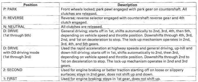
Starting is possible only in the P and N positions because of a slide-type neutral-safety switch.
Automatic Transmission (A/T) Gear Position Indicator
The A/T gear position indicator in the instrument panel shows which shift lever position has been selected without having to look down at the shift lever.
Transfer Mechanism (4WD)
The transfer mechanism consists of the transfer drive gear on the differential, the transfer shaft, the transfer drive gear (hypoid gear), the transfer output shaft (hypoid gear), and the companion flange. The transfer mechanism assembly is on the rear of the transmission, beside the differential. The transfer drive gear on the differential drives the transfer shaft and transfer drive gear (hypoid gear), and the transfer drive gear (hypoid gear) drives the transfer output shaft (hypoid gear). Power is transmitted from the transfer drive gear on the differential to the rear differential via the transfer shaft and the propeller shaft.
Clutches and Gears
The 5-speed automatic transmission uses hydraulically-actuated clutches to engage or disengage the transmission gears. When hydraulic pressure is introduced into the clutch drum, the clutch piston moves. This presses the friction discs and steel plates together, locking them so they don't slip. Power is then transmitted through the engaged clutch pack to its hub-mounted gear. Likewise, when the hydraulic pressure is bled from the clutch pack, the piston releases the friction discs and the steel plates, and they are free to slide past each other. This allows the gear to spin independently on its shaft, transmitting no power.
NOTE: The illustration shows the 4WD transmission, 2WD does not have the transfer mechanism.

1st Clutch
The 1st clutch engages/disengages 1st gear, and is located at the middle of the secondary shaft. The 1st clutch is joined back-to-back to the 3rd clutch. The 1st clutch is supplied hydraulic pressure by its ATF feed pipe within the secondary shaft.
2nd Clutch
The 2nd clutch engages/disengages 2nd gear, and is located at the end of the secondary shaft, opposite the end cover.
The 2nd clutch is supplied hydraulic pressure by a circuit connected to the internal hydraulic circuit.
3rd Clutch
The 3rd clutch engages/disengages 3rd gear, and is located at the middle of the secondary shaft. The 3rd clutch is joined back-to-back to the 1st clutch. The 3rd clutch is supplied hydraulic pressure by its ATF feed pipe within the secondary shaft.
4th Clutch
The 4th clutch engages/disengages 4th gear, as well as reverse gear, and is located at the middle of the mainshaft. The 4th clutch is joined back-to-back to the 5th clutch. The 4th clutch is supplied hydraulic pressure by its ATF feed pipe within the mainshaft.
5th Clutch
The 5th clutch engages/disengages 5th gear, and is located at the middle of the mainshaft. The 5th clutch is joined back-to-back to the 4th clutch. The 5th clutch is supplied hydraulic pressure by its ATF feed pipe within the mainshaft.
Gear operation
Gears on the mainshaft:
- 4th gear engages/disengages with the mainshaft by the 4th clutch.
- 5th gear engages/disengages with the mainshaft by the 5th clutch.
- Reverse gear engages/disengages with the mainshaft by the 4th clutch.
- Idler gear is splined with the mainshaft, and rotates with the mainshaft.
Gears on the countershaft:
- Final drive gear is integral with the countershaft.
- 1st, 2nd, 3rd, 5th, and park gears are splined with the countershaft, and rotate with the countershaft.
- 4th gear and reverse gear rotate freely from the countershaft. The reverse selector engages 4th gear and reverse gear with the reverse selector hub. The reverse selector hub is splined to the countershaft so that the 4th gear and reverse gear engage with the countershaft.
Gears on the secondary shaft:
- 1st gear engages/disengages with the secondary shaft by the 1st clutch.
- 2nd gear engages/disengages with the secondary shaft by the 2nd clutch.
- 3rd gear engages/disengages with the secondary shaft by the 3rd clutch.
- Idler gear is splined with the secondary shaft, and rotates with the secondary shaft.
The idler gear on the idler shaft transmits power between the mainshaft and the secondary shaft.
The reverse idler gear transmits power from the mainshaft reverse gear to the countershaft reverse gear, and changes rotational direction of the countershaft to reverse.
READ NEXT:
 Power Flow
P Position
Hydraulic pressure is not applied to the clutch. Power is not transmitted to
the countershaft. The countershaft is locked
by the park pawl, interlocking the park gear.
N Position
Engine po
Electronic Control System
Functional Diagram
The electronic control system consists of the powertrain control module (PCM),
sensors, and solenoid valves.
Shifting and lock-up are electronically controlled for comfortable dri
Hydraulic Controls
Valve Bodies
The valve body includes the main valve body, the regulator valve body, and
the servo body. The ATF pump is driven
by splines on the left end of the torque converter which is attached to
SEE MORE:
Seats
Component Location Index
REAR SEAT
Removal/Installation
Armrest Removal/Installation
Armrest Cover Replacement
Right Rear Seat Cover Replacement
Left Rear Seat Cover Replacement
Right Seat-back Lock Control Cable
Replacement
FRONT SEAT
Front Seat Active Head Restraint Inspect
Driving Safely With a Trailer
The added weight, length, and
height of a trailer will affect your
vehicle’s handling and performance,
so driving with a trailer requires
some special driving skills and
techniques.
For your safety and the safety of
others, take time to practice driving
maneuvers before heading for
