Honda CR-V: A/C Service Tips and Precautions
WARNING
- Compressed air mixed with the R-134a forms a combustible vapor.
- The vapor can burn or explode causing serious injury.
- Never use compressed air to pressure test R-134a service equipment or vehicle air conditioning systems.
CAUTION
- Air conditioning refrigerant or lubricant vapor can irritate your eyes, nose, or throat.
- Be careful when connecting service equipment.
- Do not breathe refrigerant or vapor.
The air conditioning system uses HFC-134a (R-134a) refrigerant and polyalkyleneglycol (PAG) refrigerant oil, which are not compatible with CFC-12 (R-12) refrigerant and mineral oil. Do not use R-12 refrigerant or mineral oil in this system, and do not attempt to use R-12 servicing equipment; damage to the air conditioning system or your servicing equipment will result.
Use only service equipment that is U.L.-listed and is certified to meet the requirements of SAE J2210 to remove R-134a from the air conditioniig system.
If accidental system discharge occurs, ventilate work area before resuming service.
R-134a service equipment or vehicle air conditioning systems should not be pressure tested or leak tested with compressed air.
Additional health and safety information may be obtained from the refrigerant and lubricant manufacturers.
- Always disconnect the negative cable from the battery whenever replacing air conditioning parts.
- Keep moisture and dirt out of the system. When disconnecting any lines, plug or cap the fittings immediately; don't remove the caps or plugs until just before you reconnect each line.
- Before connecting any hose or line, apply a few drops of refrigerant oil to the D-ring.
- When tightening or loosening a fitting, use a second wrench to support the matching fitting.
- When discharging the system, use an R-134a refrigerant recovery/recycling/charging station; don't release refrigerant into the atmosphere.
A/C Refrigerant Oil Replacement
Recommended PAG oil: SP-10
- P/N 38897-P13-A01AH: 120 mL (4 fl*oz)
- P/N 38899-P13-A01: 40 mL (1 1/3 fl*oz)
Add the recommended refrigerant oil in the amount listed if you replace any of the following parts.
- To avoid contamination, do not return the oil to the container once dispensed, and never mix it with other refrigerant oils.
- Immediately after using the oil, reinstall the cap on the container, and seal it to avoid moisture absorption.
- Do not spill the refrigerant oil on the vehicle; it may damage the paint; if it gets on the paint, wash it off immediately.
A/C condenser (including Dryer Desiccant)................ 50 mL (12/3 fl*oz)
Evaporator................................................................ 50 mL (1 2/3 fl*oz)
Line or hose.............................................................. 10 mL (1/3 fl*oz)
Receiver/Dryer
Desiccant.......................................... 10 mL (1/3 fl*oz)
Leakage repair.......................................................... 25 mL (5/6 fl*oz)
A/C compressor........................................................ Since the oil separator is
equipped inside the compressor
for this vehicle, oil drainage is
unnecessary at the time of
compressor replacement.
A/C Line Replacement

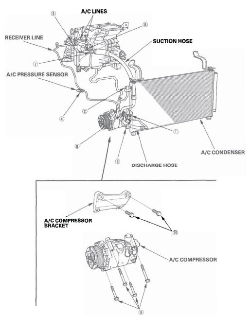
- Discharge hose to the A/C compressor (6 x 1.0 mm): 9.8 N*m (1.0 kgf*m, 7.2Ibf*ft)
- Discharge hose to the A/C condenser (6 1.0 mm): 9.8 N*m 11.0 kgf*m, 7.2Ibf*ft)
- Receiver line to the A/C condenser (6 1.0 mm): 9.8 N*m (1.0 kgf*m, 7.2Ibf*ft)
- A/C pressure sensor to receiver line (11 x 1.0 mm): 10.8 N*m 11.1 kgf*m, 8.0 Ibf*ft)
- Receiver line to the A/C line (16 1.5 mm): 13.3 N*m (1.4 kgf.m, 9.8Ibf*ft)
- A/C lines to the evaporator (6 x 1.0 mm): 9.8 N*m (1.0 kgf*m, 7.2Ibf*ft)
- A/C line to the suction hose (24 x 1.5 mm): 31.9 N*m 13.2 kgf*m, 23.5Ibf.ft)
- Suction hose to the A/C compressor 16 x 1.0 mm): 9.8 N*m (1.0 kgf*m, 7.2Ibf*ft)
- A/C compressor to the A/C compressor bracket (8 x 1.25 mm): 22 N*m (2.2 kgf*m, 16Ibf.ft)
- A/C compressor bracket to the engine block (10 x 1.25 mm): 45 N*m 14.6 kgf*m, 33.2Ibf*ft)
General Troubleshooting Information
The HVAC control unit has a self-diagnostic function for heating, ventilation, and air conditioning system. To run the self-diagnostic function, do the following:
1. Turn the ignition switch OFF and then ON (II).
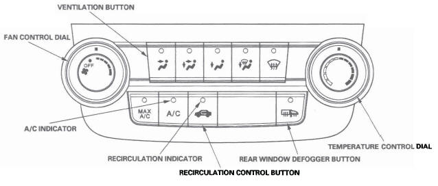
2. Set the FAN CONTROL dial OFF, the TEMPERATURE CONTROL dial on Max Cool, and select the VENT mode.
3. Turn the ignition switch OFF and then ON (II).
4. Press and hold the RECIRCULATION CONTROL button, then press the REAR WINDOW DEFOGGER button five times within 10 seconds. Release the RECIRCULATION CONTROL and REAR WINDOW DEFOGGER buttons; the recirculation indicator blinks two times, then the self-diagnostic begins.
NOTE:
- The blower motor will run at various speeds when in the self-diagnostic mode.
- In the case of multiple problems, the recirculation indicator will blink the lowest number DTC only.
- If no DTCs are found, the indicator will not blink.

Example of DTC Indication Pattern (DTC 3)


Clear the DTCs
When the problem is repaired, DTCs will automatically clear.
Max Cool Position Function
When the mode control button is in the MAX A/C position, the HVAC control unit will automatically select the recirculation mode and turn the A/C on. If the recirculation switch is pressed when in MAX A/C, MAX A/C turns off. If A/C is pressed when in MAX A/C, the A/C turns off.
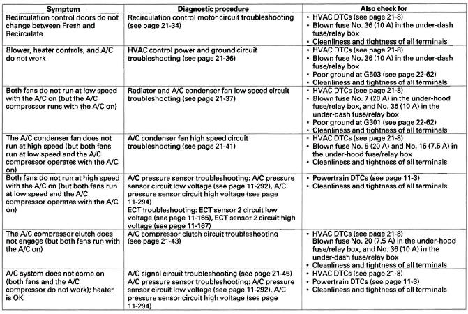
Symptom Troubleshooting Index


