Honda CR-V: System Description
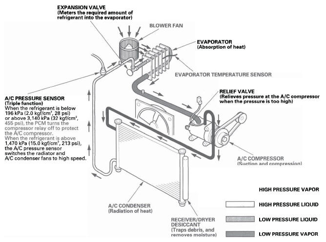
The air conditioning system removes heat from the passenger compartment by transferring heat from the ambient air to the evaporator. The evaporator cools the air with the refrigerant that is circulating through the evaporator. The refrigerant expands in the evaporator, and the evaporator becomes very cold and absorbs the heat from the ambient air. The blower fan pushes air across the evaporator where the heat is absorbed, and then it blows the cool air into the passenger compartment.
This vehicle uses HFC-134a (R-134a) refrigerant, which does not contain chlorofluorocarbons. Pay attention to the following service items:
- Do not mix refrigerants CFC-12 (R-12) and HFC-134a (R-134a). They are not compatible.
- Use only the recommended polyalkyleneglycol (PAG) refrigerant oil (SP-10) designed for the R-134a A/C compressor. Intermixing the recommended (PAG) refrigerant oil with any other refrigerant oil will result in A/C compressor failure.
- All A/C system parts (A/C compressor, discharge line, suction line, evaporator, A/C condenser, receiver/dryer, expansion valve, O-rings for joints) are designed for refrigerant R-134a. Do not exchange with R-12 parts.
- Use a halogen gas leak detector designed for refrigerant R-134a.
- R-12 and R-134a refrigerant servicing equipment are not interchangeable. Use only a recovery/recycling/charging station that is U.L.-listed and is certified to meet the requirements of SAE J2210 to service the R-134a air conditioning systems.
- Always recover refrigerant R-134a with an approved recovery/recycling/charging station before disconnecting any A/C fitting.
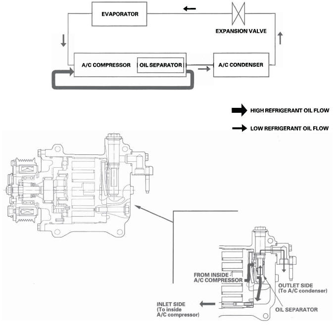
Oil Separator
Oil emission from the A/C compressor to the A/C line is reduced by placing the oil separator in the A/C compressor.
This results in a thinner oil film inside of the heat exchangers (A/C condenser and evaporator). Air conditioning efficiency is increased without sacrificing engine performance.
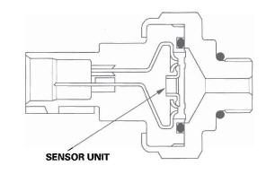
A/C Pressure Sensor
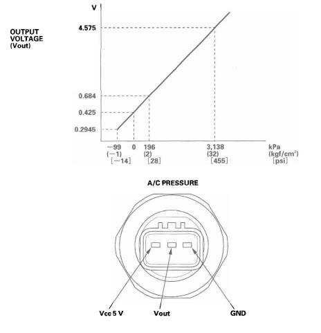
The A/C pressure sensor converts A/C pressure into electrical signals to the PCM.
NOTE: The pressures can be monitored using the HDS PGM-FI Data List.
The response of the A/C pressure sensor is shown in the graph.
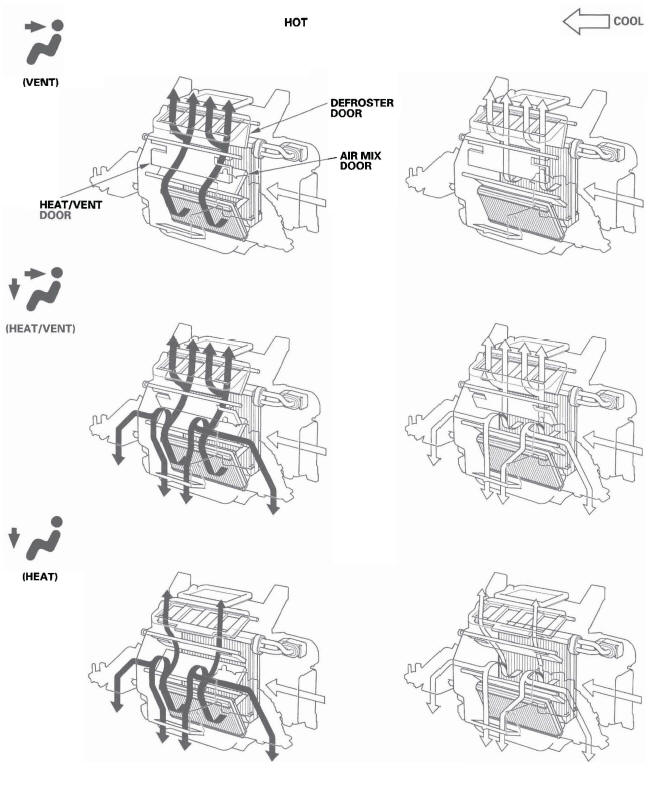
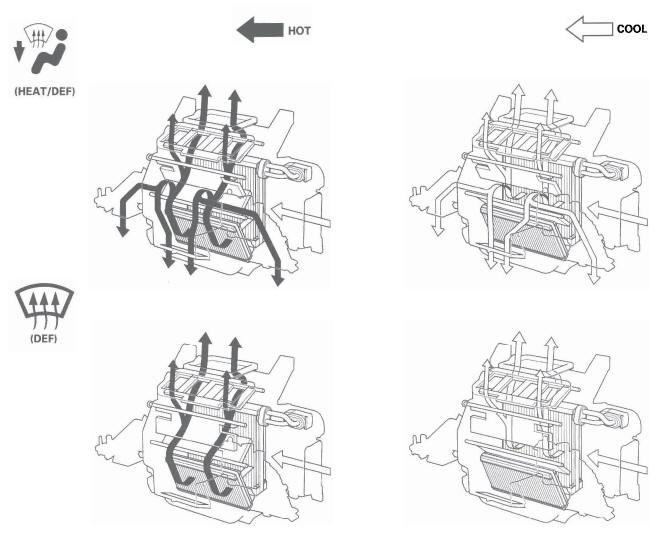
Heating/Air Conditioning Door Positions
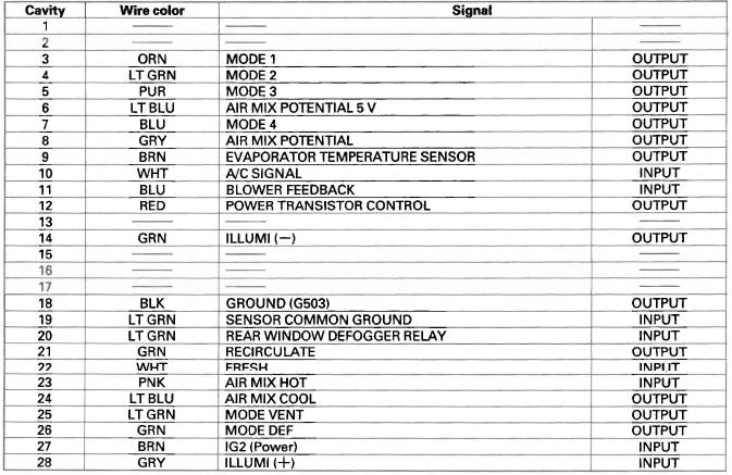
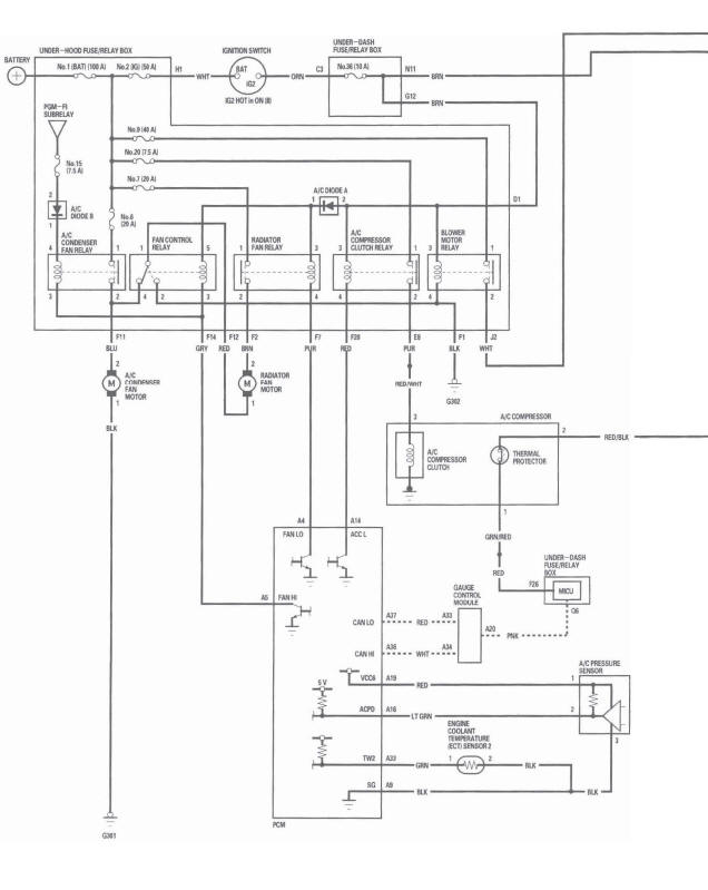
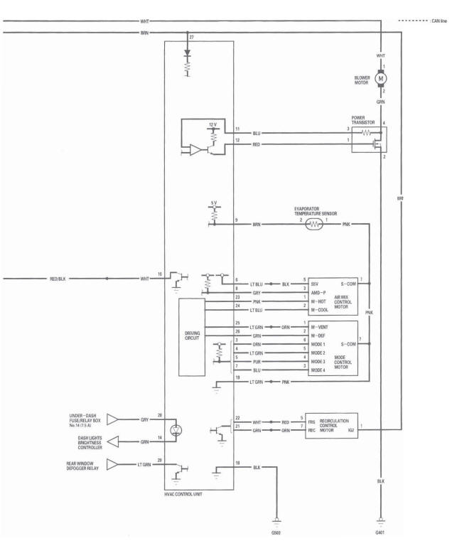
HVAC Control Unit Inputs and Outputs
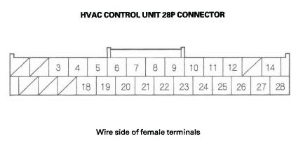
CONNECTOR A
Circuit Diagram
READ NEXT:
 DTC Troubleshooting
DTC indicator 1: An Open in the Air Mix
Control Motor Circuit
1. Start the engine.
2. Turn on the A/C, then set the temperature control
dial to Max Hot.
3. Turn the ignition switch OFF and then ON (
Recirculation Control Motor
Circuit Troubleshooting
1. Check the No. 36 (10 A) fuse in the under-dash fuse/
relay box.
Is the fuse OK?
YES-Go to step 2.
NO-Replace the fuse, and recheck. If the fuse blows again, check for a short in
the No. 36 (10 A
Radiator and A/C Condenser Fan Low Speed Circuit Troubleshooting
NOTE:
Do not use this troubleshooting procedure if the A/C
compressor is inoperative. Refer to the symptom
troubleshooting index.
Before doing symptom troubleshooting, check for
powertrain DTCs.
SEE MORE:
Using a Track List
You can also select a file directly
from a track list on the audio display.
Press the AUDIO button to show the
audio display, then touch the Track
List icon. The track list menu
appears on the display.
To scroll through the display, touch
the
or
icon on the side of the
scr
To Play a USB Flash Memory Device
This audio system can operate the
audio files on a USB flash memory
device with the same controls used
for the in-dash disc changer. To play
a USB flash memory device, connect
it to the USB adapter cable in the
upper glove box, then press the CD/
AUX or AUX button.
The audio system re
