Honda CR-V: Transmission Housing
Housing and Shaft Assembly Removal
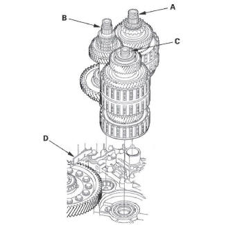
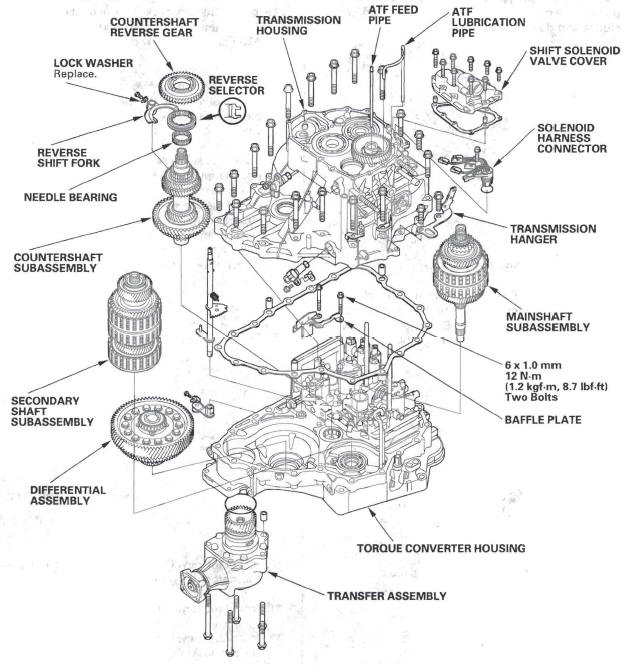
NOTE: The illustration shows the 4WD transmission; the 2WD does not have the transfer mechanism.
1. Remove the ATF feed pipe (A) from the idler gear shaft, and the ATF lubrication pipe (B) from the transmission housing.
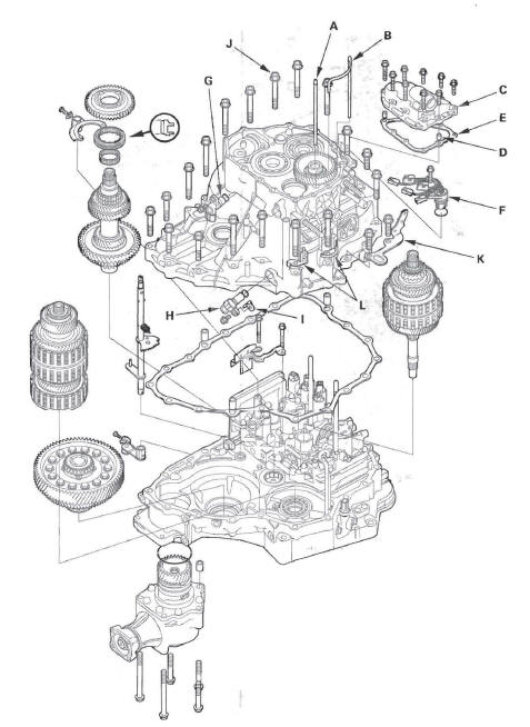
2. Remove the shift solenoid valve cover (C), dowel pins (D), and gasket (E).
3. Disconnect the connectors from shift solenoid valves, and remove the solenoid harness connector (F).
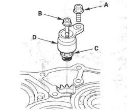
4. Remove the input shaft (mainshaft) speed sensor (G), and output shaft (countershaft) speed sensor (H) and sensor washer (I).
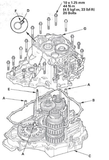
5. Remove the transmission housing mounting bolts (J) (20 bolts), transmission hanger (K), and harness clamp brackets (L).
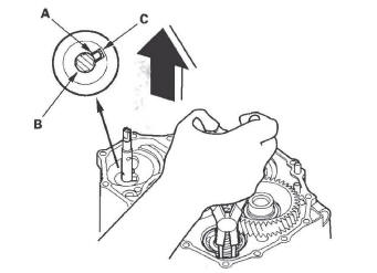
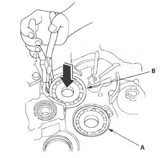
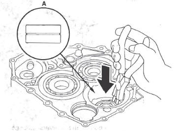
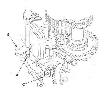
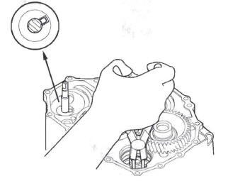
6. Align the spring pin (A) on the selector control shaft (B) with the transmission housing groove (C) by turning the control shaft with the control lever.
NOTE: Do not squeeze the end of the control shaft tips together when turning the shaft.
7. While expanding the snap ring of the secondary shaft bearing using the snap ring pliers, lift the transmission housing. Release the snap ring pliers and remove the transmission housing.
8. Remove the countershaft reverse gear and needle bearing.
9. Remove the lock bolt securing the shift fork, then remove the shift fork with the reverse selector together.
10. Remove the selector control lever from the selector control shaft.
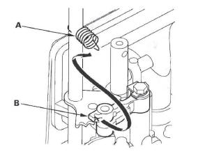
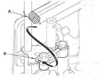
11. Unhook the detent spring (A) from the detent arm (B).
12. Remove the selector control shaft (A) from the torque converter housing.
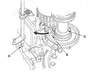
13. Turn the detent arm (B) away from the countershaft (C).
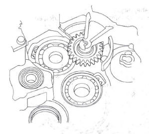
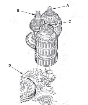
14. Remove the mainshaft subassembly (A), countershaft subassembly (B), and secondary shaft subassembly (C) together. Do not bump the countershaft on the baffle plate (D).
15. Remove the baffle plate.
16. Remove the differential assembly.
17. 4WD model: Remove the transfer assembly.
Bearing Removal
Special Tools Required
- Attachment, 78 x 90 mm 07GAD-SD40101
- Attachment, 42 x 47 mm 07746-0010300
- Driver 07749-0010000
1. Remove the idler gear shaft when removing the mainshaft bearing and idler gear shaft bearing.
NOTE: If you are only removing the countershaft bearing, idler gear shaft removal is not needed.
2. To remove the mainshaft bearing (A) and countershaft bearing (B) from the transmission housing, expand each snap ring with the snap ring pliers, then push the bearing out.
NOTE: Do not remove the snap ring unless it's necessary to clean the grooves in the housing.
3. Expand the snap ring of the idler gear shaft bearing with the snap ring pliers, then push the bearing out.
Bearing Installation
Special Tools Required
- Attachment, 78 x 90 mm 07GAD-SD40101
- Attachment, 42 x 47 mm 07746-0010300
- Driver 07749-0010000
1. Install the bearings in the direction shown.
2. Expand each snap ring with the snap ring pliers, and install the mainshaft bearing (A) and countershaft bearing (B) part-way into the housing.
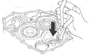
3. Release the pliers, then push the bearing down into the housing until the snap ring snaps in place around it.
4. Expand the snap ring of the idler gear shaft (A) with the snap ring pliers, and install the bearing partway into the housing.
5. Release the pliers, then push the bearing down into the housing until the snap ring snaps in place around it.
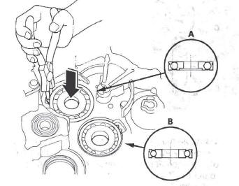
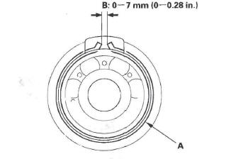
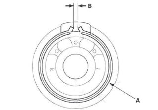
6. After installing the bearings verify that the snap rings (A) are seated in the bearing and housing grooves, and that the ring end gaps (B) are correct.
7. Install the idler shaft.
Reverse Idler Gear Removal and Installation
Removal
1. Remove the bolt (A) securing the reverse idler gear shaft holder.
2. Install a 5 x 0.8 mm bolt (B) in the reverse idler gear shaft, and pull it to remove the reverse idler gear shaft (C) and gear shaft holder (D) together.
3. Remove the reverse idler gear.
Installation
1. Install the reverse idler gear in the transmission housing.
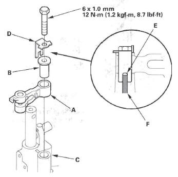
2. Lightly coat the reverse idler gear shaft (A), needle bearing (B), and new O-rings (C) with lithium grease.
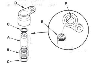
3. Assemble the new O-rings and needle bearing on the reverse idler gear shaft, then install the reverse idler gear shaft in the reverse idler gear shaft holder (D). Align the D-shaped cut out (E) of the shaft with the D-shaped area (F) of the holder.
4. Install the reverse idler gear shaft/holder assembly on the transmission housing.
Shaft Assembly and Housing Installation
NOTE: The illustration shows the 4WD transmission; the 2WD does not have the transfer assembly.
1. Install the differential assembly in the torque converter housing.
2. Install the baffle plate on the servo body.
3. Assemble the mainshaft, countershaft, and secondary shaft.
4. Join the mainshaft subassembly (A), countershaft subassembly (B), and secondary shaft subassembly (C) together, and install them in the torque converter housing. Do not bump the countershaft on the baffle plate (D).
5. Make sure if the countershaft and differential are clear of the baffle plate.
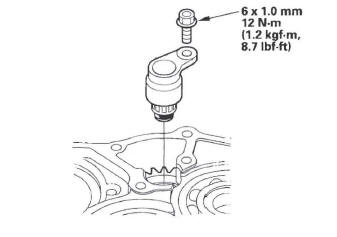
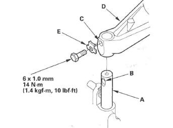
6. If the detent arm was removed, install the detent arm (A) with arm collar (B) on the servo body (C), and install the new lock washer (D) by aligning its cutout (E) with the projection (F) of the servo body.
Install and tighten the bolt, then bend the lock tab of the lock washer against the bolt head.
7. Install the control shaft (A) in the torque converter housing aligning the manual valve lever pin (B) on the control shaft with the guide of the manual valve (C). Pull the manual valve gently when aligning the manual valve with the control shaft.
8. Hook the detent arm spring (A) to the detent arm (B).
9. Turn the shift fork shaft (A) so the large chamfered hole (B) is facing the fork bolt hole (C) of the shift fork (D).
10. Install the shift fork and reverse selector together on the shift fork shaft and countershaft. Secure the shift fork to the shift fork shaft with the lock bolt and a new lock washer (E), then bend the lock tab of the lock washer against the bolt head.
11. Install the needle bearing and countershaft reverse gear on the countershaft.
12. Install the reverse idler gear in the transmission housing.
13. Install the idler gear shaft (see page 14-360), if it was removed.
14. Install the three dowel pins (A) and a new gasket (B) on the torque converter housing (C).
15. Align the spring pin (D) of the control shaft (E) with the transmission housing groove (F) by turning the control shaft. Do not squeeze the end of the control shaft tips together when turning the shaft. If the tips are squeezed together, it will cause a faulty shift position signal or position due to the play between the control shaft and the transmission range switch.
16. Place the transmission housing (G) on the torque converter housing. Do not install the input shaft (mainshaft) speed sensor and output shaft (countershaft) speed sensor before installing the transmission housing on the torque converter housing.
17. While expanding the snap ring of the secondary shaft bearing using the snap ring pliers, push the transmission housing down to start the secondary shaft bearing through the snap ring. Then release the pliers. While rotating the reverse idler gear with a screwdriver, push down the housing until it bottoms and snap ring snaps in place in the secondary shaft bearing snap ring groove.
18. Verify that the secondary shaft bearing snap ring (A) is seated in the bearing and housing groove, and check that the ring end gap (B) is 0-7 mm (0-0.28 in.)
19. Install the transmission housing mounting bolts (20 bolts) along with the transmission hanger and harness clamp brackets. Tighten the mounting bolts to 44 N*m (4.5 kgf*m, 33 Ibf.ft) in two or more steps in a crisscross pattern.
20. Install the new O-ring (A) on the input shaft (mainshaft) speed sensor (B), and install the input shaft (mainshaft) speed sensor in the transmission housing.
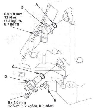
21. Install the new O-ring (C) on the output shaft (countershaft) speed sensor (D), and install the output shaft (countershaft) speed sensor and sensor washer (E).
22. Install the new O-ring (F) on the shift solenoid harness connector (G), and install the shift solenoid harness connector in the transmission housing.
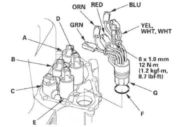
23. Connect the harness terminals to the solenoids:
- RED wire connector to shift solenoid valve E.
- GRN wire connector to shift solenoid valve C.
- ORN wire connector to shift solenoid valve B.
- BLU wire connector to shift solenoid valve A
- VEL, WHT, WHT wire connector to shift solenoid valve D.
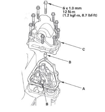
24. Install the new gasket (A), dowel pins (B), and shift solenoid valve cover (C), and secure the cover with the bolts.
READ NEXT:
 Valve Body
Valve Body and ATF Strainer Removal
NOTE: The illustration shows the 4WD transmission; the 2WD is similar.
1. Remove the ATF feed pipes (A) and ATF joint pipes (B).
2. Remove the ATF strainer (C) (t
Torque Converter Housing
Mainshaft Bearing and Oil Seal
Replacement
Special Tools Required
Adjustable bearing puller, 25-40 mm
07736-A01000B or 07736-A01000A
Attachment, 62 x 68 mm 07746-0010500
Attachment, 72 x 75 mm 0
Shafts and Clutches
Mainshaft Disassembly, Inspection, and Reassembly
1. Inspect the thrust needle bearing and the needle bearing for galling and
rough movement.
2. Inspect the splines for excessive wear and damage.
3
SEE MORE:
DTC P0453: FTP Sensor Circuit High Voltage
NOTE: Before you troubleshoot, record all freeze data and any on-board
snapshot, and review the general troubleshooting information.
1. Turn the ignition switch ON (II).
2. Clear the DTC with the HDS.
3. Turn the ignition switch OFF.
4. Remove the fuel fill cap.
5. Turn the ignition switch ON
Braking System
Your vehicle is equipped with disc
brakes at all four wheels. A power
assist helps reduce the effort needed
on the brake pedal. The anti-lock
brake system (ABS) helps you retain
steering control when braking very
hard.
Resting your foot on the pedal keeps
the brakes applied lightly, b
