Honda CR-V: Torque Converter Housing
Mainshaft Bearing and Oil Seal Replacement
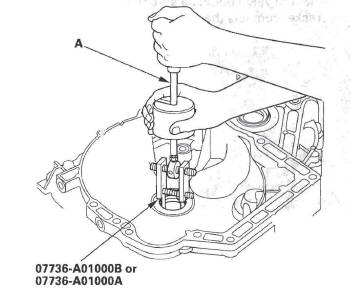
Special Tools Required
- Adjustable bearing puller, 25-40 mm 07736-A01000B or 07736-A01000A
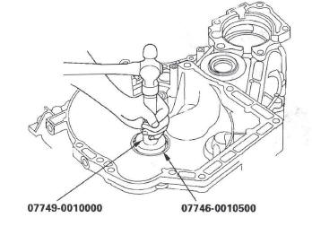
- Attachment, 62 x 68 mm 07746-0010500
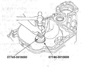
- Attachment, 72 x 75 mm 07746-0010600
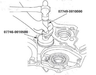
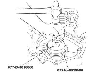
- Driver 07749-0010000
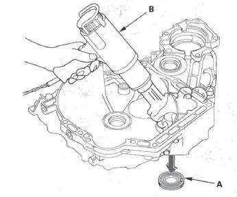
1. Remove the mainshaft bearing and oil seal using the adjustable bearing puller and a commercially available 3/8 "-16 slide hammer (A).
2. Install the new mainshaft bearing until it bottoms in the torque converter housing using the driver and the attachment (62 x 68 mm).
3. Install the new oil seal flush with the housing using the driver and the attachment (72 x 75 mm).
Countershaft Bearing Replacement
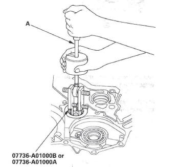
Special Tools Required
- Adjustable bearing puller, 25-40 mm 07736-A010008 or 07736-A01000A
- Driver 07749-0010000
- Attachment, 62 x 68 mm 07746-0010500
1. Remove the countershaft bearing using the adjustable bearing puller and a commercially available 3/8 "-16 slide hammer (A).
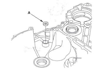
2. Remove the ATF guide plate (A), and check it for wear and damage. If the guide plate is worn or damaged, replace it.
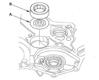
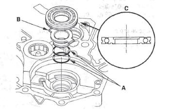
3. Install the ATF guide plate in the housing, and install the new countershaft bearing (B).
4. Install the bearing securely in the housing using the driver and the attachment (62 x 68 mm).
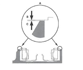
5. Make sure that the bearing outer race notch-cut (A) is installed at a height of 0-0.05 mm (0-0.002 in.) (B) above the housing surface (C). Do not install the bearing higher than 0.05 mm (0.002 in.) above the housing surface.
Secondary Shaft Bearing Replacement
Special Tools Required
- Driver 07749-0010000
- Attachment, 62 x 68 mm 07746-0010500
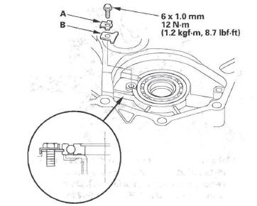
1. Remove the bolt, then remove the lock washer (A) and bearing set plate (B).
2. Remove the secondary shaft bearing (A) by heating the housing to about 212 ºF (100 ºC) with a heat gun (B). Do not heat the housing in excess of 212 ºF (100 ºC).
NOTE: Let the housing cool to normal temperature before installing the bearing.
3. Install the new O-rings (A) on the ATF guide collar (B), then install the ATF guide collar in the housing.
4. Install the new secondary shaft bearing (C) in the direction shown.
5. Install the bearing in the housing securely using the driver and the attachment (62 x 68 mm).
6. Check that the bearing groove aligns with the housing surface, then install the bearing set plate with aligning the bearing groove.
7. Install the new lock washer and bolt, then bend the lock tab of the lock washer against the bolt head.
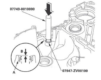
Selector Control Shaft Oil Seal Replacement
Special Tools Required
- Driver 07749-0010000
- Oil seal driver attachment 07947-ZV00100
1. Remove the oil seal (A) from the torque converter housing.
2. Install the new oil seal (A) in the torque converter housing to a depth of 0.5-1.5 mm (0.02-0.06 in.) (B) below the housing surface using the driver and the oil seal driver attachment.
READ NEXT:
 Shafts and Clutches
Mainshaft Disassembly, Inspection, and Reassembly
1. Inspect the thrust needle bearing and the needle bearing for galling and
rough movement.
2. Inspect the splines for excessive wear and damage.
3
A/T Differential
Component Location Index
4WD
2WD
Backlash Inspection
NOTE: The illustration shows the 4WD model; 2WD is
similar.
1. Install the drive shaft and intermediate shaft into
the differential assembly.
2
Transfer Assembly Inspection/Disassembly/Reassembly
Inspection
1. Set the dial indicator (A) on the companion flange
(B).
2. Measure the transfer gear backlash.
Standard: 0.06-0.16 mm (0.02-0.06 in.)
3. Secure the transfer housing (A) in a bench vise
SEE MORE:
Audio Unit Removal/Installation
Without navigation
SRS components are located in this area. Review the
SRS component location.
Also review the precautions and procedures in the SRS section before doing repairs or
service.
NOTE:
Put on gloves to protect your hands.
Take care not to scratch the dashboard and related
parts.
Lay
Replacing a High-mount Brake Light Bulb
1. Open the tailgate.
Unlatch the top of the cover by
pulling back on it with your hands.
2. Place a cloth on the side edge of
the cover to prevent scratches.
Remove the cover by carefully
prying on the edge with a small
flat-tip screwdriver and pulling the
cover off.
3. Remove the
