Honda CR-V: Transfer Assembly Inspection/Disassembly/Reassembly
Inspection
1. Set the dial indicator (A) on the companion flange (B).
![]()
2. Measure the transfer gear backlash.
Standard: 0.06-0.16 mm (0.02-0.06 in.)
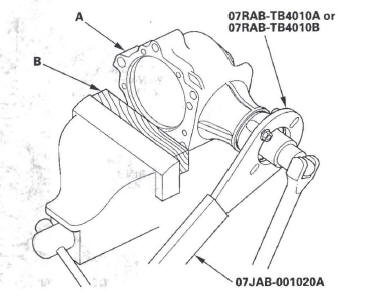
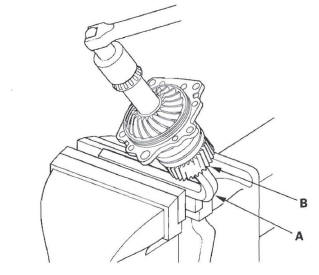
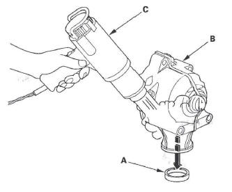
3. Secure the transfer housing (A) in a bench vise (B) with soft jaws. To prevent damage to the transfer housing, always use soft jaws or equivalent materials between the transfer housing and the vise.
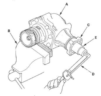
4. Rotate the companion flange several times to seat the tapered roller bearings.
5. Measure the starting torque at the companion flange (C) with a torque wrench (D) and a socket (E).
Standard: 2.44-3.87 N*m
(24.8-39.4 kgf*cm, 21.5-34.1 Ibf*in.)
6. Remove the transfer assembly from the vise.
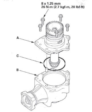
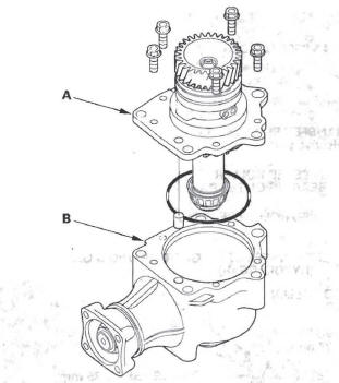
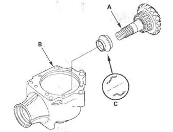
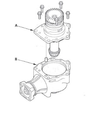
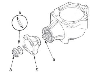
7. Remove the transfer holder (A) from the transfer housing (B), then remove the O-ring (C) from the transfer holder.
8. Apply Prussian Blue to both side of the transfer drive gear teeth lightly and evenly.
9. Install the transfer holder, and tighten the bolts. Do not install the O-ring on the transfer holder.
10. Rotate the companion flange in both directions until the transfer gears rotate one full turn in both directions.
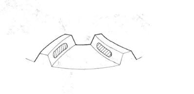
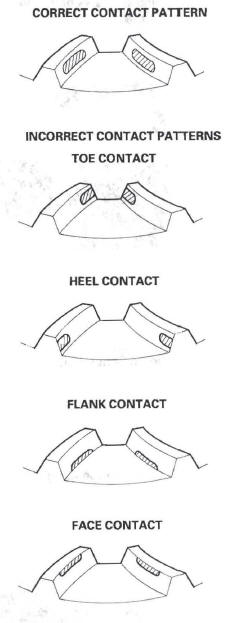
11. Remove the transfer holder, and check the transfer drive gear tooth contact pattern. The pattern should be centered on the gear teeth as shown.
12. If the measurements are out of standard or the tooth contact pattern are incorrect, disassemble the transfer assembly and repair.
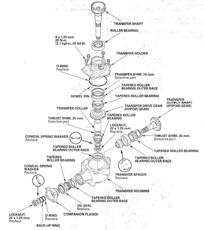
Disassembly
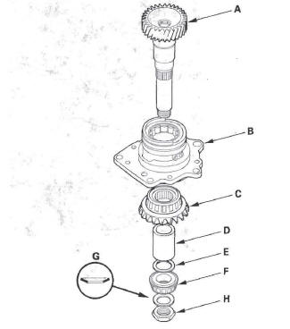
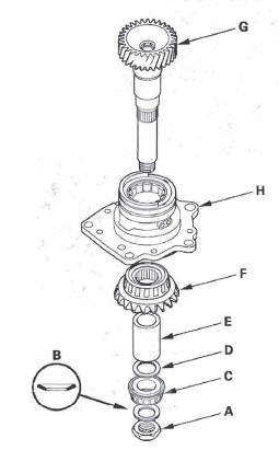
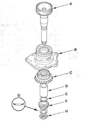
Exploded View
Special Tools Required
- Holder handle 07JAB-001020A
- Companion flange holder 07RAB-TB4010A or 07RAB-TB4010B
NOTE: Refer to the Exploded View as needed during the following procedure.
1. Remove the transfer holder (A) from the transfer housing (B).
2. Cut the lock tab on the locknut using a chisel.
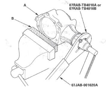
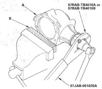
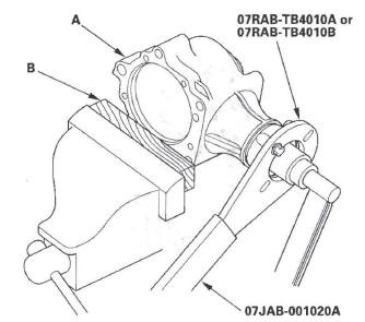
3. Secure the transfer housing (A) in a bench vise (B) with soft jaws. To prevent damage to the transfer housing, always use soft jaws or equivalent materials between the transfer housing and the vise.
4. Install the companion flange holder on the companion flange, then loosen the locknut.
5. Remove the companion flange holder.
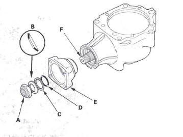
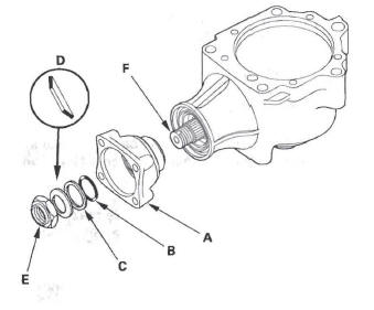
6. Remove the locknut (A), conical spring washer (B), back-up ring (C), O-ring (D), and companion flange (E) from the transfer output shaft (F).
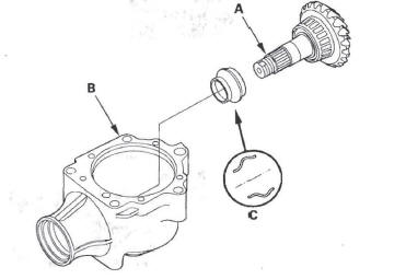
7. Remove the transfer output shaft (A) from the transfer housing (B), then remove the transfer spacer (C) from the transfer output shaft.
8. Remove the oil seal (A) and tapered roller bearing (B) from the transfer housing (C).
Transfer Holder Disassembly
1. Cut the lock tab on the locknut of the transfer shaft using a chisel.
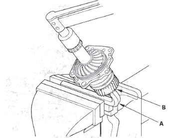
2. Put a 14 mm hex wrench (A) in the transfer shaft (B), then secure the hex wrench in a bench vise.
3. Remove the locknut (A) and conical spring washer (B).
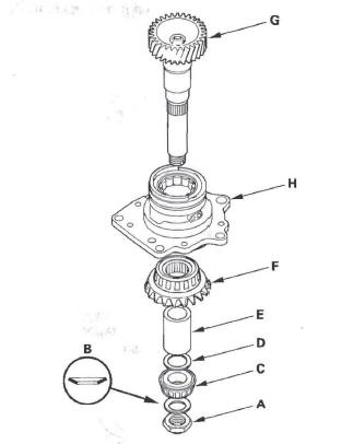
4. Remove the tapered roller bearing (C), 25 mm thrust shim (D), transfer collar (E), transfer drive gear (F), and transfer shaft (G) from the transfer holder (H).
Transfer Holder Roller Bearing Replacement
Special Tools Required
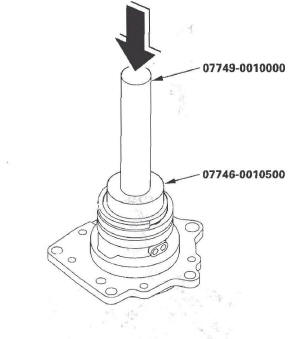
- Attachment, 62 x 68 mm 07746-0010500
- Driver 07749-0010000
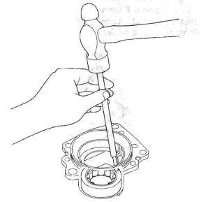
1. Remove the roller bearing from the transfer holder.
2. Install the new roller bearing in the transfer holder using the driver and the attachment (62 x 68 mm).
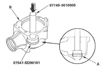
Transfer Holder Tapered Roller Bearing Outer Race Removal/Installation
Special Tools Required
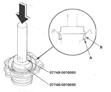
- Attachment, 72 x 75 mm 07746-0010600
- Driver 07749-0010000
1. Remove the tapered roller bearing outer race (A) and 75 mm thrust shim (B) from the transfer holder.
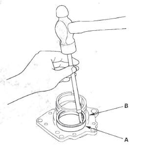
2. Install the 75 mm thrust shim (A) in the transfer holder, then install the tapered roller bearing outer race (B) using the driver and the attachment (72 x75 mm).
Transfer Drive Gear Bearing Replacement
Special Tools Required
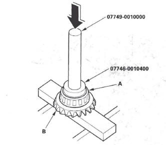
- Attachment, 52 x 55 mm 07746-0010400
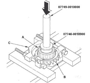
- Attachment, 40 x 42 mm 07746-0010900
- Driver 07749-0010000
1. Remove the tapered roller bearing (A) from the transfer drive gear (B) using the driver, the attachment (40 x 42 mm), bearing separator (C) and a press.
2. Install the new tapered roller bearing (A) on the transfer drive gear (B) using the driver, the attachment (52 x 55 mm), and a press.
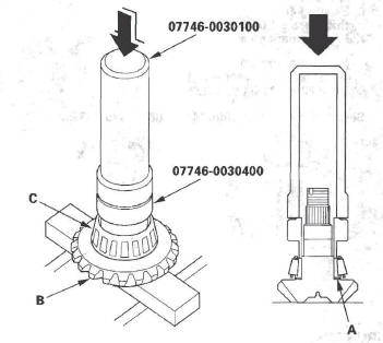
Transfer Output Shaft Bearing Removal/Installation
Special Tools Required
- Driver, 40 mm I.D. 07746-0030100
- Attachment, 35 mm I.D. 077 46-0030400
1. Remove the tapered roller bearing (A) from the transfer output shaft (B) with the bearing separator (C) and a press. Place a shaft protector (D) between the transfer output shaft and the press to prevent damaging the transfer output shaft.
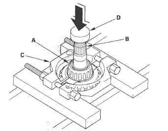
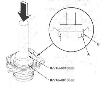
2. Install the 35 mm thrust shim (A) on the transfer output shaft (B).
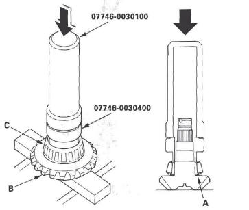
3. Install the tapered roller bearing (C) on the transfer output shaft using the driver (40 mm I.D.), the attachment (35 mm I.D.), and a press.
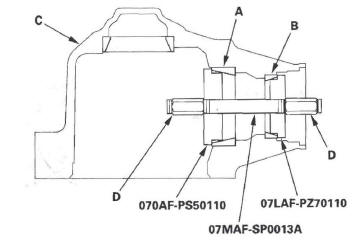
Transfer Housing Tapered Roller Bearing Outer Race Replacement
Special Tools Required
- Tapered bearing outer race attachment 070AF-PS50110
- Bearing installer attachment 07LAF-PZ70110
- Installer shaft 07MAF-SP0013A
- Oil seal driver attachment 07947-SD90101
- Driver 07749-0010000
NOTE: Replace the bearing with a new one whenever the outer race is replaced.
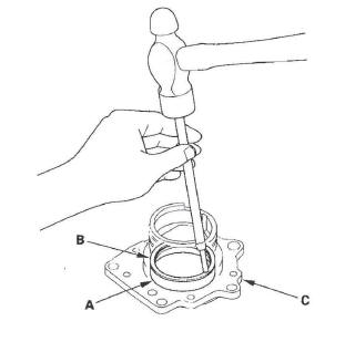
1. Remove the 57 mm bearing outer race (A) from the transfer housing (B).
NOTE: Some 57 mm bearing outer races are press-fitted in the housing. The 62 mm bearing outer race (C) and 50.3 mm bearing outer race (D) are press-fitted, and the press-fitted outer races must be removed by heating the housing.
![]()
2. Remove the press-fitted bearing outer race (A) from the transfer housing (B) by heating the housing to about 212 F (100 C) with a heat gun (C). Do not heat the housing more than 212 F (100 C).
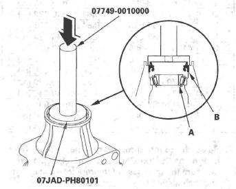
3. Install the 57 mm bearing outer race (A) in the transfer housing (B) using the driver and the oil seal driver attachment.
4. Install the 62 mm bearing outer race (A) and 50.3 mm bearing outer race (B) in the transfer housing (C), set the attachments over the races, and install the installer shaft through the attachments.
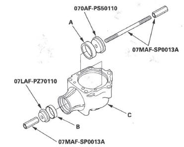
5. Tighten the installer shaft nut (D) to install the races (A) (B) into the transfer housing securely.
Reassembly
Special Tools Required
- Oil seal driver attachment 07JAD-PH80l0l
- Companion flange holder
07RAB-TB4010A or 07RAB-TB4010B
- Holder handle 07JAB-001020A
- Attachment, 72 x 75 mm 07746-0010600
- Driver, 40 mm I.D. 07746-0030100
- Attachment, 35 mm I.D. 07746-0030400
- Driver 07749-0010000
NOTE:
- While reassembling the transfer assembly:
- Check and adjust the transfer gear tooth contact.
- Measure and adjust the transfer gear backlash.
- Check and adjust the tapered roller bearing starting torque.
- Coat all parts with ATF during reassembly.
- Replace the tapered roller bearing and the bearing outer race as a set if either part is replaced.
- Replace the transfer drive gear and the transfer output shaft as a set if either part is replaced.
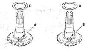
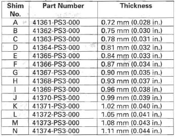
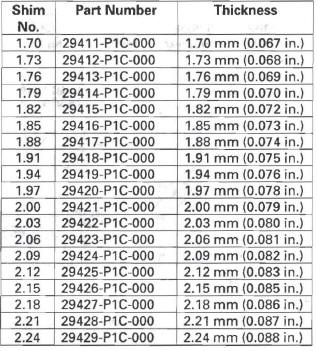
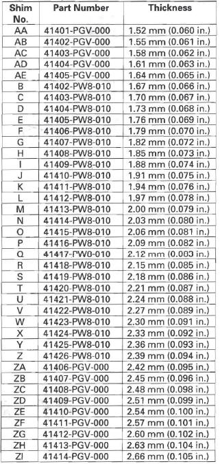
1. Select the 35 mm thrust shim if the transfer output shaft is replaced. Calculate the thickness of the 35 mm thrust shim using the formula, and select the shim from the table.
NOTE: The number on the transfer output shaft is shown in 1/100 mm.
![]()
A: Number on the existing transfer output shaft
B: Number on the replacement transfer output shaft
C: Thickness of the existing 35 mm thrust shim
X: Thickness needed for the replacement 35 mm
thrust shim
Example
A: Existing transfer output shaft (hypoid gear)
Number = +2
B: Replacement transfer output shaft (hypoid gear)
Number = -1
C: Existing 40 mm thrust shim
thickness = 1.05 mm
X: Replacement 40 mm thrust shim thickness
X = A/100-B/100+C
= 2/100-(-1)100+1.05
= 0.02+0.01+1.05 = 1.08 (mm)
Select 35 mm thrust shim M of 1.08 mm (0.043 in.)
THRUST SHIM, 35 mm
2. Select the 35 mm thrust shim if the tapered roller bearing on the transfer output shaft is replaced.
Measure the thickness of the replacement bearing and the existing bearing, and calculate the difference of the bearing thickness. Adjust the thickness of the existing 35 mm thrust shim by the amount of the difference in bearing thickness, and select the replacement 35 mm thrust shim from the table.
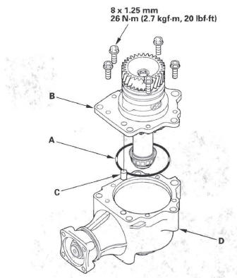
3. Install the 35 mm thrust shim (A) on the transfer output shaft (B), then install the tapered roller bearing (C) using the driver (40 mm I.D.), the attachment (35 mm I.D.), and a press.
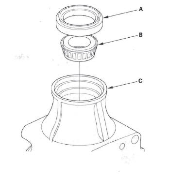
4. Place the tapered roller bearing (A) on the bearing outer race of the companion flange side of the transfer housing.
5. Install the new oil seal (B) on the transfer housing using the driver and the oil seal driver attachment.
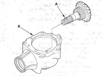
6. Install the output shaft (A) in the transfer housing (B). Do not install the transfer spacer on the transfer output shaft.
7. Install the companion flange (A), conical spring washer (B), and locknut (C) on the transfer output shaft (D). Do not install the O-ring and back-up ring.
8. Secure the transfer housing (A) in a bench vise (B) with soft jaws. To prevent damage to the transfer housing, always use soft jaws or equivalent materials between the transfer housing and the vise.
9. Install the companion flange holder on the companion flange.
10. Tighten the locknut while measuring the starting torque so the starting torque is within 0.98-1.39 N*m (10.0-14.2 kgf*cm, 8.7-12.3 Ibf*in.). Do not stake the locknut in this step. Remove the companion flange holder.
11. Install the transfer shaft (A) in the transfer holder (B), and install the transfer drive gear (C), transfer collar (D), 25 mm thrust shim (E), tapered roller bearing (F), conical spring washer (G), and locknut (H).
12. Put a 14 mm hex wrench (A) in the transfer shaft (B), then secure the hex wrench in a bench vise.
13. Tighten the locknut 118 N*m (12.0 kgf*m, 87 Ibf*ft).
Do not stake the locknut in this step.
14. Apply Prussian Blue to both sides of the transfer drive gear teeth lightly and evenly.
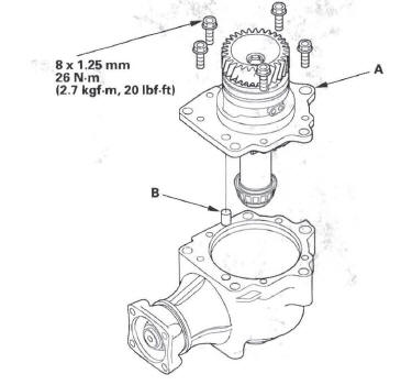
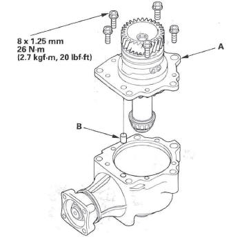
15. Temporarily install the transfer holder (A) and dowel pin (B) without O-ring, and tighten the bolts.
16. Rotate the companion flange in both directions until the transfer gears rotate one full turn in both directions.
17. Set a dial indicator (A) on the companion flange (B).
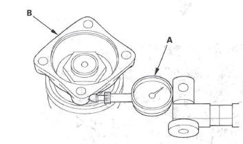
18. Measure the transfer gear backlash.
Standard: 0.06-0.16 mm (0.02-0.06 in.)
19. Remove the transfer holder, and check the transfer drive gear tooth contact pattern.
20. If the backlash measurement is out of standard, adjust the backlash with the 35 mm thrust shim and recheck. Do not use more than two 35 mm thrust shims to adjust the backlash.
21. If the transfer gear tooth contact is incorrect, adjust the tooth contact with the 25 mm or 35 mm thrust shim. Do not use more than two of each thrust shim to adjust the tooth contact.
- Toe Contact
Use a thicker 35 mm thrust shim to move the transfer output shaft toward the transfer drive gear. Because this movement causes the transfer gear backlash to change, move the transfer drive gear away from the transfer output shaft to adjust the transfer gear backlash as follows:- Increase the thickness of the 25 mm thrust shim.
- Reduce the thickness of the 75 mm thrust shim by the amount you increased the 25 mm thrust shim.
- Heel Contact
Use a thinner 35 mm thrust shim to move the transfer output shaft away from the transfer drive gear. Because this movement causes the transfer gear backlash to change, move the transfer drive gear toward the transfer output shaft to adjust the transfer gear backlash as follows:- Reduce the thickness of the 25 mm thrust shim
- Increase the thickness of the 75 mm thrust shim by amount you reduced the thickness of the 25 mm thrust shim.
- Flank Contact
Use a thinner thrust shim to move the transfer drive gear toward the transfer output shaft. Flank contact must be adjusted with in the limits of the transfer gear backlash. If the backlash exceeds the limits, adjust as described under Heel Contact. - Face Contact
Use a thicker thrust shim to move the transfer drive gear away from the transfer output shaft.Face contact must be adjusted within the limits of the transfer gear backlash. If the backlash exceeds the limits, adjust as described under Toe Contact.
THRUST SHIM, 25 mm
22. Remove the transfer holder (A) from the transfer housing (B) after adjusting the transfer gear backlash or transfer gear tooth contact.
23. Secure the transfer housing (A) in a bench vise (B) with soft jaws. To prevent damage to the transfer housing, always use soft jaws or equivalent materials between the transfer housing and the vise.
24. Install the companion flange holder on the companion flange, loose the locknut, and remove the companion flange holder.
25. Remove the locknut (A), conical spring washer (B), and companion flange (C) from the transfer driven gear (B).
26. Remove the transfer output shaft (A) from the transfer housing (B).
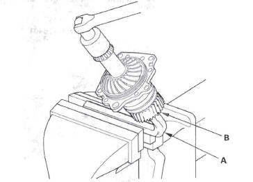
27. Install the new transfer spacer (C) on the transfer output shaft in the direction shown, and install them in the transfer housing.
28. Coat the threads of the locknut and transfer output shaft with ATF.
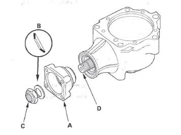
29. Install the companion flange (A), new O-ring (B), back-up ring (C), new conical spring washer (B), and new locknut (E) on the transfer output shaft (F).
Install the conical spring washer in the direction shown.
30. Secure the transfer housing (A) in a bench vise (B) with soft jaws. To prevent damage to the transfer housing, always use soft jaws or equivalent materials between the transfer housing and the vise.
31. Install the companion flange holder on the companion flange.
32. Tighten the locknut while measuring the starting torque of the transfer output shaft.
Starting torque: 0.98-1.39 N*m (10.0-14.2 kgf*cm, 8.7-12.3Ibf*in.)
Tightening torque: 132-260 N*m (13.5-26.5 kgf*m, 97.6-192Ibf*ft)
NOTE:
- Rotate the companion flange several turns to seat the tapered roller bearings, then measure the starting torque.
- If the starting torque exceeds 1.39 N*m (14.2 kgf*cm, 12.3 Ibf*in.), replace the transfer spacer and reassemble the parts. Do not adjust the starting torque with the locknut loose.
- If the tightening torque exceeds 260 N*m (26.5 kgf*m, 192Ibf*ft), replace the transfer spacer and reassemble the parts.
33. Remove the companion flange holder.
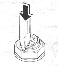
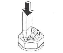
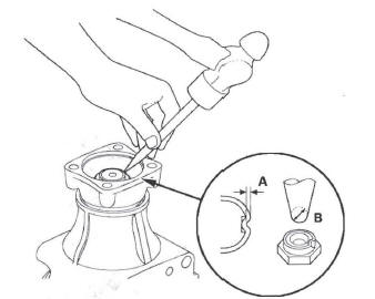
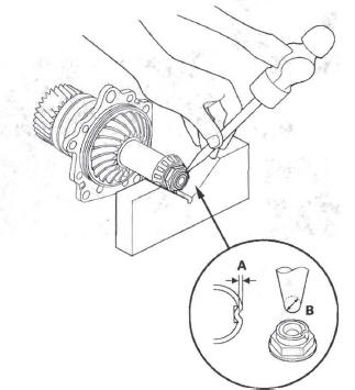
34. Stake the locknut into the transfer output shaft in depth (A) of 0.7-1.2 mm (0.03-0.05 in.) using a 3.5 mm punch (B).
35. Temporarily install the transfer holder (A) and dowel pin (B) without O-ring, and tighten the bolts.
36. Secure the transfer housing (A) in a bench vise (B) with soft jaws. To prevent damage to the transfer housing, always use soft jaws or equivalent materials between the transfer housing and the vise.
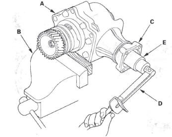
37. Rotate the companion flange several times to seat the tapered roller bearing.
38. Measure the starting torque at the companion flange (C) using a torque wrench (D) and a socket (E).
Standard: 2.44-3.87 N*m (24.8-39.4 kgf*cm, 21.5-34.1 Ibf*in.)
39. Remove the transfer holder from the transfer housing.
40. If the measurement is within the standard, go to step 53.
41. If the measurement is out of standard, put a 14 mm hex wrench (A) in the transfer shaft (B), then secure the hex wrench in a bench vise.
42. Loosen the locknut.
43. Remove the locknut (A) and conical spring washer (B).
44. Remove the tapered roller bearing (C), 25 mm thrust shim (D), transfer collar (E), transfer drive gear (F), and transfer shaft (G) from the transfer holder (H).
45. Remove the tapered roller bearing outer race (A) and the 75 mm thrust shim (B) from the transfer holder (C).
46. Measure the thickness of the 75 mm thrust shim, and select the new 75 mm thrust shim.
THRUST SHIM, 75 mm
47. Install the new 75 mm thrust shim (A) in the transfer holder, then install the tapered roller bearing outer race (B) using the driver and the attachment (72 x 75 mm).
48. Install the transfer shaft (A) in the transfer holder (B), and install the transfer drive gear (C), transfer collar (D), 25 mm thrust shim (E), tapered roller bearing (F), conical spring washer (G), and locknut (H). Install the conical spring washer in the direction shown.
49. Put a 14 mm hex wrench (A). in the transfer shaft (B), then secure the hex wrench in a bench vise.

50. Tighten the locknut 118 N*m (12.0 kgf*m, 87 Ibf*ft).
Do not stake the locknut in this step.
51. Temporarily install the transfer holder (A) and dowel pin (B) without the O-ring, and tighten the bolts.
52. Rotate the companion flange several turns to seat the tapered roller bearings, and recheck the starting torque. Remove the transfer holder after adjusting the starting torque.
53. Stake the locknut into the transfer shaft in depth (A) of 0.7-1.2 mm (0.03-0.05 in.) using a 3.5 mm punch (B).
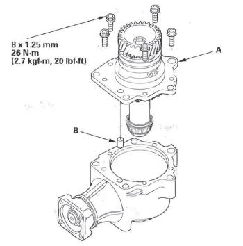
54. Install the new O-ring (A) on the transfer holder (B), then install the transfer holder with the dowel pin (C) on the transfer housing (D).
READ NEXT:
 Rear Differential
Special Tools
Holder Handle
Oil Seal Driver
Attachment, 78 x 80 mm
Attachment, 52 x 55 mm
Companion Flange Holder
Driver
Component Location Index
REAR DIFFERENTIAL MOUNT
Replacement
System Description
Outline
The rear differential has a real-time 4WD control mechanism that enables 4WD
by transmitting appropriate driving
force from the front wheels to the rear wheels when necessary. It uses a
real
Dual Pump System Function Test
Starting and accelerating in forward gears
(4WD mode)
NOTE: Do not test repeatedly or the fluid will overheat.
1. Lift up the vehicle so all four wheels are off the ground.
2. Make a mark (A) on eit
SEE MORE:
Rear Differential Fluid Inspection and
Replacement
1. With the vehicle on level ground, inspect the
differential fluid with the ignition switch turned to
LOCK (0).
2. Use solvent and a brush to wash off any oil and dirt
from the differential fluid inspection oil filler plug.
3. Remove the oil filler plug (A) and the sealing
washer (B), then check
Hydraulic Flow
Distribution of Hydraulic Pressure
As the engine turns, the ATF pump starts to operate. Automatic transmission
fluid (ATF) is drawn through the ATF
strainer (filter) and discharged into the hydraulic circuit. Then, ATF flowing
from the ATF pump becomes line pressure
that is regulated by the regula
